20
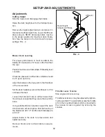
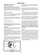
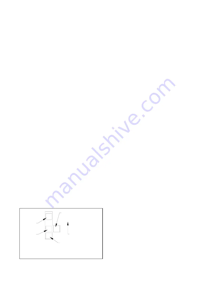
By moving the levers an equal amount forward or
back the machine will move in a straight line in
that direction. FIG - 8
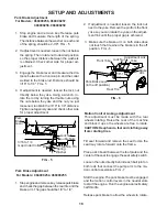
Movement of either lever forward will cause the
right or left wheel to rotate in a forward direction.
To stop movement pull both levers into the neutral
position.
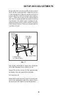
To turn right while moving in a forward direction
pull the right lever back towards the neutral posi-
tion, this will slow the rotation of the right wheel
and cause the machine to turn in that direction.
To turn left while moving in a forward direction pull
the left lever back towards the neutral position,
this will slow the rotation of the left wheel and
cause the machine to turn in that direction.
To zero turn pull one lever back beyond neutral
while holding the other slightly ahead of neutral.
NOTE: The direction of the zero turn will be deter-
mined by which lever is pulled back beyond neu-
tral. Thus left lever back, left zero turn and oppo-
site for right zero turn.
Use extra care when us-
ing this maneuver the machine can spin very
rapidly if one lever is positioned too far ahead
of the other.
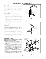
The tracking knob is located in front of the left con-
trol lever. Rotating this knob allows fine tuning
adjustments so that the machine tracks straight
with the drive levers in the full forward position.
Rotate the knob clockwise (as viewed from the
operating position) to increase the speed or coun-
terclockwise to decrease the speed on the left
control lever. Example: If control levers are full for-
ward and the unit turns to the right, turn the track-
ing knob counterclockwise to decrease the speed
on the left control lever.
OPERATION
Starting and operation
Operator must be sitting in the seat. Engage the
park brake, blades disengaged and the motion
control levers in the neutral slots.
Set choke (if needed) turn key and release as soon
as engine starts. Adjust throttle to half and shut
choke off.
Release parking brake.
Close motion control levers.
Engage blades and set RPM to maximum. CAU-
TION: Be sure all persons are clear of the area
before engaging blades.
CONTROLS
Be familiar with all controls their function and how
to operate them before starting the machine.
Motion Control Levers
Motion control levers on each side of the console
control the direction of movement. The left lever
controls the flow of oil from the left hydro pump to
the left wheel motor. The right lever controls the
flow of oil from the right hydro pump to the right
wheel motor.
NOTE: To begin motion the operator must be in
the seat and the parking brake disengaged before
the motion control levers can be moved from the
neutral slots or the engine will kill.
FIG - 8
Operating instructions
Motion Control Lever Pattern
(Right Side)
FIG - 8
Roll Bar and Seat Belt
Operate the unit with the roll bar in the raised and
locked position and use seat belt. There is no
rollover protection when the roll bar is down. If it is
necessary to lower roll bar do not wear the seat
belt. Raise the roll bar as soon as clearance per-
mits.
Neutral Slot
Neutral Lock
Front of
Mower
Reverse
Neutral
Forward
Tracking
Summary of Contents for 968999207 / iZ5223KAA
Page 2: ...2 2004 Husqvarna All right reserved Beatrice NE Printed U S A ...
Page 28: ...28 WIRING DIAGRAMS ...
Page 29: ...29 WIRING DIAGRAMS ...
Page 30: ......


