7
2. OPERATING INSTRUCTIONS
HOW THE HAMMER OPERATES
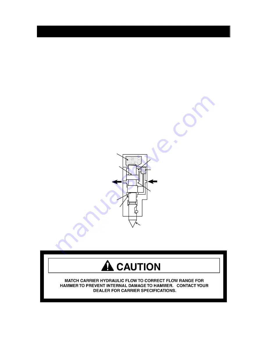
The main valve (Figure 1) for the hammer is built into the cylinder. Hydraulic oil is
supplied into the hammer through this valve. During the upward stroke, the pressure in
the upper chamber is released via the main valve and through the outlet. High pressure in
the lower chamber then forces the piston upward.
As soon as the piston reaches the upper end of the stroke, the main valve directs flow to
the upper chamber causing it to become high pressure.
Since surface
A
is greater than surface
B
, the piston is driven downward with the help of
the accumulated energy from the gas chamber, creating the impact stroke of the hammer.
At the point of impact, the main valve shifts, releasing the high pressure from the upper
chamber, enabling the upward stroke to occur again.
Figure 1. Principles of Operation.
(Refer to Table 10 page 26.)
GAS
CHAMBER
PRESSURE
RECIEVING
SURFACE A
PRESSURE
RECIEVING
SURFACE B
LOWER CHAMBER
(HIGH PRESSURE)
TOOL
MIDDLE CHAMBER
(LOW PRESSURE)
BUILT-IN MAIN
VALVE
UPPER CHAMBER
(VARIABLE
PRESSURE)
Summary of Contents for HH100
Page 1: ...HUSKIE HYDRAULIC HAMMERS SERVICE MANUAL HH100 HH150 2 HH300 2 HH500 2 HH750 2 HH1000 2 ...
Page 2: ...2 ...
Page 33: ...33 9 PARTS LIST AND ILLUSTRATIONS HH100 HH150 2 HH300 2 HH500 2 HH750 2 HH1000 2 ...
Page 35: ...35 HH100 HAMMER Effective 07 09 ...
Page 37: ...37 ...
Page 39: ...39 HH150 2 HAMMER S N 001 099 2B2 1000 UP Effective 07 09 ...
Page 41: ...41 ...
Page 43: ...43 HH300 2 HAMMER S N 001 099 2E2 1000 UP Effective 07 09 ...
Page 47: ......
Page 49: ...49 HH500 2 HAMMER S N 001 099 2R2 1000 UP Effective 07 09 ...
Page 55: ...55 HH750 2 HAMMER S N 001 099 2F2 1000 UP Effective 07 09 ...
Page 59: ...59 ...
Page 61: ...61 Effective 07 09 HH1000 2 HAMMER S N 001 099 2H2 1000 UP ...


