


Hunter 31 • DC Electric
7.3
Each battery bank is wired to a battery selector switch
located under the chart table. A circuit breaker “DC Main”
on the battery switch panel connects the batteries to the
electrical system. The batteries supply power, first to
the battery selector switch then to the 12 Volt DC Panel
which distributes power to such equipment as cabin
lights, instruments, and accessories.
The negative terminal of all banks are attached to the DC
Ground connection on the engine. This system, known as
the negative ground system, is the approved system for
marine DC electrical systems. The battery wiring system
has two color coded wires. The yellow wire is the ground
(negative), and the red wire is (positive).
To avoid explosions, do not use jumper cables and a
booster battery to start the engine. If batteries are dead,
then remove and recharge them ashore.
Batteries produce hydrogen and oxygen gasses when
they are being charged. These explosive gasses escape
through the vent/fill caps and may form an explosive
atmosphere around the battery if ventilation is poor. This
gas may remain around the battery for several hours after
charging. Sparks or flame can ignite the gas and cause
an explosion.
The following precautions must be taken:
The wiring to the batteries must have proper over
current protection in the form of fuse or breakers.
Use only battery chargers that have been listed by a
testing agency, such as Underwriters Laboratories,
Inc.
Follow the wiring diagrams exactly.
To remove the battery:
Turn off all power drawing breakers and isolate bat-
tery.
Remove negative (-) cable first, then the positive (+).
When you install a battery, the battery connections must
be made properly.
Attach the positive cable to the positive (+) terminal
on the battery.
Attach the negative cable to the negative (-) terminal
•
•
•
1.
2.
1.
2.
on the battery.
Note: Batteries should always be removed and installed by
trained, qualified persons to avoid all damages.
Table 1 Recommended Batteries
(or equivalent)
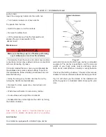
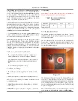
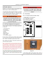
7.2.2 Battery Switch Panel
The battery banks are connected to a battery selector
switch (Fig. 7.1 shown without optional inverter) located
under the chart table.
The selector switches are marked as to which battery
they control. Turning the selector switch to the Off posi-
tion turns power off to the respective circuits, likewise, the
On position turns power on.
Figure 7.1
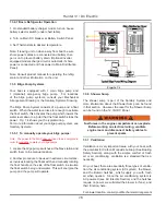
The battery switch panel houses the breakers for some
of the main components in your DC system. The breaker
controls are marked at the switch panel, and control sys-
tems or components on your boat that require a connec-
tion that remains energized even through the Main Panel
may be de-energized.
The breakers and switches are described in greater detail
in the “Breakers and Switches” section of this chapter.
MFG/PN
Group Size
Volts
Qty
Exide Pre-
vailer PV-31
31
12
2
Summary of Contents for H31
Page 1: ...Operator s Operator s Manual Manual H31 H31 V1 031507 P N 1031379 ...
Page 2: ......
Page 9: ...Introduction Introduction H31 H31 Chapter 1 Chapter 1 V1 031507 P N 1031379 ...
Page 14: ...Hunter 31 Introduction 1 6 Notes ...
Page 15: ...V1 031507 P N 1031379 and Documents Documents Forms Forms H31 H31 Chapter 2 Chapter 2 ...
Page 26: ...Hunter 31 Documents and Forms Maintenance Log Date Maintenance Performed Hourmeter 2 12 ...
Page 27: ...Hunter 31 Documents and Forms 2 13 Date Maintenance Performed Hourmeter Maintenance Log ...
Page 33: ...Hunter 31 Documents and Forms 2 19 Spare Parts List ...
Page 34: ...Hunter 31 Documents and Forms Dates of practice drills and onboard safety inspections 2 20 ...
Page 35: ...Hunter 31 Documents and Forms 2 21 My personal preferences for maintenance items safety gear ...
Page 36: ...Hunter 31 Documents and Forms Notes 2 22 ...
Page 37: ...V1 031507 P N 1031379 Warranty Warranty H31 H31 Chapter 3 Chapter 3 ...
Page 38: ...This Page Intentionally Left Blank Hunter Warranty 3 2 ...
Page 45: ...Boating Boating Safety Safety H31 H31 Chapter 4 Chapter 4 V1 031507 P N 1031379 ...
Page 64: ...This Page Intentionally Left Blank Hunter 31 Boating Safety 4 20 ...
Page 65: ...Chapter 5 Chapter 5 Fuel Fuel Systems Systems H31 H31 V1 031507 P N 1031379 ...
Page 71: ...A Quick Fuel Filter Reference Hunter 31 Fuel Systems 5 7 Fig 5 6 ...
Page 76: ...Notes Hunter 31 Fuel Systems 5 12 ...
Page 79: ...Underwater Underwater Gear Gear H31 H31 Chapter 6 Chapter 6 V1 031507 P N 1031379 ...
Page 80: ...Hunter 31 Underwater Gear 6 2 This Page Intentionally Left Blank ...
Page 89: ...Hunter 31 Underwater Gear 6 11 ...
Page 91: ...DC Electric DC Electric Systems Systems H31 H31 Chapter 7 Chapter 7 V1 031507 P N 1031379 ...
Page 100: ...Hunter 31 DC Electric 7 10 Notes ...
Page 105: ...AC Electric AC Electric Systems Systems H31 H31 Chapter 8 Chapter 8 V1 031507 P N 1031379 ...
Page 112: ...Hunter 31 AC Electric Systems 8 8 Notes ...
Page 114: ...Hunter 31 AC Electric Systems 8 10 Notes ...
Page 115: ...Water Water Systems Systems H31 H31 Chapter 9 Chapter 9 V1 031507 P N 1031379 ...
Page 122: ...Hunter 31 Water Systems 9 8 Notes ...
Page 123: ...Waste Waste Systems Systems H31 H31 Chapter 10 Chapter 10 V1 031507 P N 1031379 ...
Page 132: ...Hunter 31 10 10 Waste System Bilge Water ...
Page 134: ...Hunter 31 Waste and Sanitation Systems 10 12 Notes ...
Page 143: ...Hunter 31 11 9 Exhaust System ...
Page 144: ...Hunter 31 Engine and Transmissions 11 10 Notes ...
Page 145: ...V1 031507 P N 1031379 Sails Sails Rigging H31 H31 Chapter 12 Chapter 12 and and ...
Page 150: ...Hunter 31 Sails and Rigging 12 6 Notes ...
Page 154: ...Hunter 31 12 10 Jib Furling Line Layout ...
Page 155: ...Hunter 31 12 11 Optional Mainsheet Purchase Traveler Layout ...
Page 156: ...Hunter 31 12 12 Arch Installation ...
Page 157: ...Hunter 31 12 13 Lazyjack Installation ...
Page 158: ...Hunter 31 12 14 Optional Spinnaker Layout ...
Page 159: ...Getting Getting Underway Underway H31 H31 Chapter 13 Chapter 13 V1 031507 P N 1031379 ...
Page 166: ...Hunter 31 Getting Underway 13 8 Notes ...
Page 167: ...Maintenance H31 H31 Chapter 14 Chapter 14 V1 031507 P N 1031379 ...
Page 180: ...Hunter 31 Maintenance 8 8 Notes ...
Page 181: ...Glossary Glossary H31 H31 Chapter 15 Chapter 15 V1 031507 P N 1031379 ...


