


Hunter 31 • Sails and Rigging
12.3
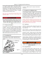
12.4 The Sails
As standard your Hunter is equipped with a furling jib
sail and a drop down main sail. The mainsail is the sail
attached to the aft track of the mast and hoisted with the
main halyard from the cockpit. The jib sail is attached to
the forestay and like the mainsail hoisted with the jib hal-
yard from the cockpit.
Most Hunter sailboats feature the control of the most
important sail controls from the cockpit. In addition to the
main and jib halyard you will find a main sheet line with
a winch at the aft edge of the cockpit together with the
vang and or outhaul control (some optional). The jib is
controlled with the jib sheet control lines lead back to the
cockpit coming either side. In addition the jib furling line
located to the starboard side of the cockpit allows the
safe and easy unfurling and furling in of the jib sail.
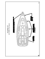
12.5 Reefing Instructions
1. Run both reefing lines as illustrated in the boom &
reef layout. The shorter reef line will be used on the first
reef (Starboard Side, Green). The longer reef line on the
second reef (Port Side, Red).
2. Raise the main sail.
3. Ease the mainsheet and vang.
4. Lower the main sail to approximately the first reef
position.
5. Take up the slack in the first reef line until the tack and
the clew are down to about 2” above the boom.
6. Adjust the main halyard so that the tack reef point is
not contacting the goose neck on the front of the spar
and is applying tension to the luff of the main above the
reef, not below. There will be approximately 6” (150mm)
of stretch in the main luff and main halyard when the reef-
ing line is tensioned, so, make sure that this is allowed
for when adjusting the main halyard to locate the tack
reef block.
7. Confirm that the tack reef point is still clear of the tack
shackle and that only the main luff above the reef cringle
is tensioned, not the luff between the cringle and the top
stacked sail slide. Ease the reef line and readjust the
halyard if necessary.
8. Mark the halyard at the stopper with 1” (25mm) single
band of indelible marker ink. By dropping the halyard to
this mark every time, positioning is made easier. The hal-
yard is automatically in the correct position for the reef.
9. Repeat the procedure for the second reef, using double
bands to mark the halyard in the correct position.
12.6 Reefing Procedure
1. Head up into the wind.
2. Ease the mainsheet and vang.
3. Check the topping lift for adequate boom support.
4. Lower the main halyard to the appropriate mark and
snub the line with the stopper.
5. Tension the reefing line with the self-tailing winch until
the reef clew is brought down to the boom. Apply stopper
and tension the main halyard back up, ease the topping
lift (if needed).
12.7 Shaking Out a Reef
1. Head up into the wind.
2. Ease the mainsheet and vang. Release the tension on
the topping. Lift (if needed).
3. Release the line stopper and remove reef line from
winch.
4. Tension the main halyard to raise sail, making sure reef
lines run freely while sail is being raised. Apply stopper
to main halyard.
5. Re-tension vang and mainsheet, ease the topping lift
(if needed).
12.8 Spinnaker (Optional)
To set the optional spinnaker using the dedicated halyard,
first attach the halyard to the head ring on the sail. Next,
tie the tack downhaul line to the tack ring, lead it through a
turning block on the deck near the bow, and run it aft to the
cockpit. Set up the tack downhaul so the tack of the sail is
about five inches above the deck when the sail is hoisted.
Attach the spinnaker sheet to the clew ring of the spinna-
ker and make sure the line is led aft outside the lifelines
to a turning block on the toerail located just forward of
the stern pulpit. Then run it forward to a winch allowing
Summary of Contents for H31
Page 1: ...Operator s Operator s Manual Manual H31 H31 V1 031507 P N 1031379 ...
Page 2: ......
Page 9: ...Introduction Introduction H31 H31 Chapter 1 Chapter 1 V1 031507 P N 1031379 ...
Page 14: ...Hunter 31 Introduction 1 6 Notes ...
Page 15: ...V1 031507 P N 1031379 and Documents Documents Forms Forms H31 H31 Chapter 2 Chapter 2 ...
Page 26: ...Hunter 31 Documents and Forms Maintenance Log Date Maintenance Performed Hourmeter 2 12 ...
Page 27: ...Hunter 31 Documents and Forms 2 13 Date Maintenance Performed Hourmeter Maintenance Log ...
Page 33: ...Hunter 31 Documents and Forms 2 19 Spare Parts List ...
Page 34: ...Hunter 31 Documents and Forms Dates of practice drills and onboard safety inspections 2 20 ...
Page 35: ...Hunter 31 Documents and Forms 2 21 My personal preferences for maintenance items safety gear ...
Page 36: ...Hunter 31 Documents and Forms Notes 2 22 ...
Page 37: ...V1 031507 P N 1031379 Warranty Warranty H31 H31 Chapter 3 Chapter 3 ...
Page 38: ...This Page Intentionally Left Blank Hunter Warranty 3 2 ...
Page 45: ...Boating Boating Safety Safety H31 H31 Chapter 4 Chapter 4 V1 031507 P N 1031379 ...
Page 64: ...This Page Intentionally Left Blank Hunter 31 Boating Safety 4 20 ...
Page 65: ...Chapter 5 Chapter 5 Fuel Fuel Systems Systems H31 H31 V1 031507 P N 1031379 ...
Page 71: ...A Quick Fuel Filter Reference Hunter 31 Fuel Systems 5 7 Fig 5 6 ...
Page 76: ...Notes Hunter 31 Fuel Systems 5 12 ...
Page 79: ...Underwater Underwater Gear Gear H31 H31 Chapter 6 Chapter 6 V1 031507 P N 1031379 ...
Page 80: ...Hunter 31 Underwater Gear 6 2 This Page Intentionally Left Blank ...
Page 89: ...Hunter 31 Underwater Gear 6 11 ...
Page 91: ...DC Electric DC Electric Systems Systems H31 H31 Chapter 7 Chapter 7 V1 031507 P N 1031379 ...
Page 100: ...Hunter 31 DC Electric 7 10 Notes ...
Page 105: ...AC Electric AC Electric Systems Systems H31 H31 Chapter 8 Chapter 8 V1 031507 P N 1031379 ...
Page 112: ...Hunter 31 AC Electric Systems 8 8 Notes ...
Page 114: ...Hunter 31 AC Electric Systems 8 10 Notes ...
Page 115: ...Water Water Systems Systems H31 H31 Chapter 9 Chapter 9 V1 031507 P N 1031379 ...
Page 122: ...Hunter 31 Water Systems 9 8 Notes ...
Page 123: ...Waste Waste Systems Systems H31 H31 Chapter 10 Chapter 10 V1 031507 P N 1031379 ...
Page 132: ...Hunter 31 10 10 Waste System Bilge Water ...
Page 134: ...Hunter 31 Waste and Sanitation Systems 10 12 Notes ...
Page 143: ...Hunter 31 11 9 Exhaust System ...
Page 144: ...Hunter 31 Engine and Transmissions 11 10 Notes ...
Page 145: ...V1 031507 P N 1031379 Sails Sails Rigging H31 H31 Chapter 12 Chapter 12 and and ...
Page 150: ...Hunter 31 Sails and Rigging 12 6 Notes ...
Page 154: ...Hunter 31 12 10 Jib Furling Line Layout ...
Page 155: ...Hunter 31 12 11 Optional Mainsheet Purchase Traveler Layout ...
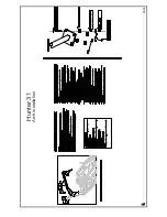
Page 156: ...Hunter 31 12 12 Arch Installation ...
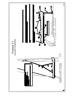
Page 157: ...Hunter 31 12 13 Lazyjack Installation ...
Page 158: ...Hunter 31 12 14 Optional Spinnaker Layout ...
Page 159: ...Getting Getting Underway Underway H31 H31 Chapter 13 Chapter 13 V1 031507 P N 1031379 ...
Page 166: ...Hunter 31 Getting Underway 13 8 Notes ...
Page 167: ...Maintenance H31 H31 Chapter 14 Chapter 14 V1 031507 P N 1031379 ...
Page 180: ...Hunter 31 Maintenance 8 8 Notes ...
Page 181: ...Glossary Glossary H31 H31 Chapter 15 Chapter 15 V1 031507 P N 1031379 ...


