22
®
41343-01 7/1/2002
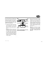
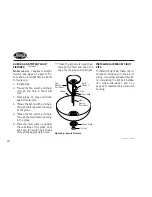
Figure 8d - Multi-Light Fixture
Cup
Globe
Silencer
Band
Thumb-
screw
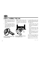
7. Connect the upper plug connec-
tor from the motor to the lower
plug connector in the lower
switch housing assembly. See Fig-
ure 7f.
Note:
Both plug connectors are
polarized and will only fit together
one way. Make sure that both
connectors are properly aligned
before connecting them together.
Incorrect connection could cause
improper operation and damage
to the product.
8. Place the lower switch housing
assembly over the upper switch
housing. Align the side screw
holes in the upper and lower
switch housings. Attach the lower
switch housing to the upper
switch housing with three #6-32
x 3/8" housing assembly screws.
See Figure 7f.
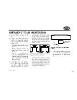
Globe
Thumbscrew
Bulb
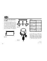
Figure 8c - Single-Globe Fixture
INSTALLING SINGLE-GLOBE
FIXTURE BULB AND GLOBE
Refer to Figure 8c.
1.
Install light bulbs.
2.
Insert the globe around the bulb
and into the fixture. Install and
tighten thumbscrews manually.
Do not overtighten.
INSTALLING INTEGRATED MULTI-
LIGHT FIXTURE BULBS AND
GLOBES
Refer to Figure 8d.
1. Place silencer band around the
neck of each globe.
2. Insert globe in cup.
3. Install and tighten thumbscrews
manually. Do not overtighten.
4. Install bulbs.
Summary of Contents for Fan
Page 2: ...2 41343 01 7 1 2002 ...

