


17
41343-01 6/12/2002
®
41343-01 7/1/2002
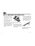
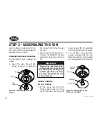
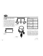
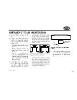
STEP 7 - ATTACHING THE SWITCH HOUSING
Figure 7a - Attaching Upper Switch
Housing to Switch Housing Mounting
Plate
Housing
Assembly
Screw
Switch
Housing
Mounting
Plate
Upper Plug
Connector
Upper
Switch
Housing
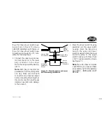
Figure 7b - Mounting the Upper
Switch Housing
CAUTION
Make sure the upper switch
housing is securely attached to
the switch housing mounting
plate. Failure to properly at-
tach and tighten all three hous-
ing assembly screws could re-
sult in the switch housing and
light fixture falling.
The switch housing is made up of two
sections: the upper switch housing,
and the lower switch housing.
ATTACHING THE UPPER SWITCH
HOUSING
1. Partially install two #6-32 x 3/8"
housing assembly screws into the
switch housing mounting plate as
shown in Figure 7a.
2. Feed the upper plug connector
through the center opening of the
upper switch housing. See Figure
7a.
3. Align the keyhole slots in the up-
per switch housing with the hous-
ing assembly screws installed in
sub-step 1.
4. Turn the upper switch housing
counterclockwise until the hous-
ing assembly screws are firmly
situated in the narrow end of the
keyhole slots as shown in Figure
7b. Install the one remaining #6-
32 x 3/8" housing assembly screw
into the third hole in the upper
switch housing. Tighten all three
screws firmly.
continued
Summary of Contents for Fan
Page 2: ...2 41343 01 7 1 2002 ...