background image

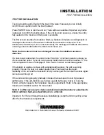
Pressing VIEW again will select the Monster Digits View, which 
increases the size of key digital information so that it can be 
viewed from a great distance. Normal 2D information is 
displayed on the right side of the display. Pressing VIEW again 
will toggle the display back to the 2D view. 
 
If a Wide Side transducer is being used (see Using Alternative 
Transducers), the VIEW button is used to select one of four 
views available: Both, Left, Right, and Down. You can select 
"side" simulator to view this presentation even if a Wide Side 
transducer is not connected. 
 
The three lower buttons, MENU, UP ARROW, and DOWN 
ARROW work together to control the Wide Paramount menu-
controlled user functions. Initially, there will be 8 user menus available. If you find that there are menus 
which are seldom used, these can be "hidden" from the normal menu sequence to simplify operation. 
 
MENU brings a menu on-screen for adjustment. In normal operation, pressing MENU repeatedly will cycle 
through all available menus. A menu remains on-screen for several seconds allowing user adjustment by 
means of the ARROW keys. If no adjustment is made in the allotted time, the menu disappears. If you 
need the menu to remain onscreen longer to study the adjustment options, press and hold MENU to keep 
the menu on-screen indefinitely. Once you release the MENU button, the menu will time out. 
 
Once a menu times out, it is still considered the active menu. The Active menu icon is displayed at the top 
left corner of the display in most modes. Pressing MENU will bring up the active menu. The UP ARROW 
and DOWN ARROW make adjustments to menu functions. On the left side of every menu there are UP 
ARROW and DOWN ARROW symbols. The symbols indicate which ARROW button has a function in a 
particular situation. Either one or both ARROW buttons can be used to adjust the menu function. A light 
gray ARROW symbol means that the corresponding ARROW button has no function. Pressing that button 
will result in no adjustment and the "error" audible will be heard. A black ARROW symbol means that the 
corresponding ARROW button can be used to affect the menu adjustment. 
 
The ARROW buttons often can be used when no menu is on-screen. In these situations, pressing the 
ARROW button affects the function of the active (last-used) menu. This is a short-cut to menu operation. 
An abbreviated menu appears on-screen while the adjustment is made and "times out". A frequently used 
menu can be adjusted very quickly using this technique. 
 
After an adjustment is made to a menu function, the menu "times out" after several seconds and the unit 
returns to normal operation. The sequence in which the menus appear is adjusted by the order that the 
menus are used. The last menu used will always appear first. The second most recently used menu will 
appear second, etc. This "automatic sequencing" ensures that the most recently used menus will always 
appear first, and menus which have not recently been adjusted will appear later in the sequence. 
All menus use the same basic layout as shown in Figure F. The heading at the top describes the menu 
function (see Control Functions for more details on individual functions).  
 
The UP ARROW and DOWN ARROW symbols to the left of the menu indicate which buttons are 
available for adjustment. In menus which have numerous possible settings such as depth range, a range 
of adjustment indicator shows the total range available and the current setting. Within the menu are the 
options available. The selected option or current setting is highlighted in the black box. If no adjustment is 
made, this will be the selected setting. Pressing one of the ARROW buttons while the menu is on-screen 
selects another option. After the adjustment is made, the menu will time out and go off-screen. A Bird 
note will normally appear briefly to confirm the adjustment. 
 
Several of the menus are multi-step. In some situations if an adjustment is made, additional options 
become available for further adjustment. Examples of these multi-step menus are Depth Range, Depth 
Alarm and Zoom. See the detailed description of each function for further explanation. 
 
The one menu option which functions differently than previously described is the Options menu. User 
Options is a group of functions which are used initially to select user preferences. The Options are not 
normally needed during operation of the unit. Options differ from the other menu functions in that once 

Summary of Contents for Wide Paramount

Page 1: ......

Page 2: ...our number listed in the Customer Support section INSTALLATION OVERVIEW Your Humminbird fishfinder consists of two primary components to install the control head and the transducer The control head c...

Page 3: ...should the boat strike debris in the water or when trailering As an alternative to transom mounting it is possible on many fiberglass hulled boats to glue the transducer on the inside of the boat hull...

Page 4: ...other surface Trolling Motor Mounting The standard transducer can also be adapted to mount on most trolling motors using a different accessory kit This accessory includes a bracket and hose clamp that...

Page 5: ...minbird fishfinder The installation guide included on the next few pages provides detailed step by step instructions for installation of the control head and transducer For transom mount transducer in...

Page 6: ...the propeller s This turbulent water is normally confined to areas immediately aft of ribs strakes or rows of rivets on the bottom of the boat and in the immediate area of the propeller s Figure 1 On...

Page 7: ...g a 5 32 4mm bit drill the two holes to a depth of approximately 1 3cm On fiberglass hulls it is best to start with a smaller bit and use progressively larger drill bits to reduce the chance of chippi...

Page 8: ...ation after high speed testing 1 First adjust the pivot angle of the transducer body so its length is parallel with the length of hull of the boat Then pivot the transducer down so the rear is about 1...

Page 9: ...erference If the cable is too short extension cables are available to extend the transducer cable up to a total of 50 15 m Call Humminbird Customer Support for more information Follow these steps to r...

Page 10: ...hull to install the transducer Consider the following to find the best location Observe the outside of the boat hull to find the areas that are mostly free from turbulent water Avoid ribs strakes and...

Page 11: ...dry the mounting surface If the surface is excessively rough it may be necessary to sand the area to provide a smooth mounting surface Ensure the mounting area is clear and dry 3 Mix an ample quantit...

Page 12: ...y supported to protect the fishfinder from excessive wave shock and vibration and provide visibility while in operation The mounting area should allow sufficient room for the unit to pivot and swivel...

Page 13: ...holes Figure 22 Note if the cables must pass through the mounting surface at a different location drill the 1 25mm hole at that location and pass the cables through from underneath Also you must break...

Page 14: ...ll the excess cable from beneath the mounting surface so the connector holder aligns with the mounting holes on the front of the mounting bracket Figure 27 3 Snap the support plate to the rear of the...

Page 15: ...rmal operation unless you choose another option If you do not press any button before the timer reaches 0 the normal operation screen is displayed If the boat is in water sonar data appears If the bot...

Page 16: ...l cannot pass through air Refer to the troubleshooting section of this manual If the unit is working properly gradually increase the boat speed to test high speed performance If the unit functions wel...

Page 17: ...r to retain user settings selected when in simulator mode If no transducer is detected the unit defaults to pre selected options when powered off WHAT YOU SEE ON SCREEN Your Wide Paramount uses a 240...

Page 18: ...default view when the Temp Speed sensor is connected Water surface temperature and boat speed are displayed at the bottom of the screen If the Wide Paramount determines that a Wide Side transducer is...

Page 19: ...e bottom depiction is narrow and dense If the bottom is soft mud or sand the depiction will be thick and less dense This indicates that much of the signal is absorbed by the soft bottom If the bottom...

Page 20: ...ible to distinguish fish size between varying species The signal intensity is normalized for depth so that a small fish close to the boat does not appear as a large fish symbol This Fish ID function c...

Page 21: ...several screen configurations or views possible depending on the transducer in use When using the standard Tribeam transducer the VIEW button toggles the display between the full screen 2D View Conto...

Page 22: ...menu adjustment The ARROW buttons often can be used when no menu is on screen In these situations pressing the ARROW button affects the function of the active last used menu This is a short cut to me...

Page 23: ...bias This prevents the display from being cluttered with sonar returns from debris or suspended particles In very clear or very deep water it may be desirable to increase the sensitivity bias since ev...

Page 24: ...multiple chirps will be heard and no further adjustment is allowed When Manual range is used the unit no longer adjusts the Depth Range to the most appropriate range for bottom display Often the bott...

Page 25: ...the Zoom range In Auto Zoom the box will move vertically to remain in the general area of the bottom return The left side of the screen is a magnified view of the information seen inside the Zoom ran...

Page 26: ...until the Triplog menu is on screen Use the UP ARROW to select Hide and let the menu time out The Triplog continues to operate and log time and distance even when it is not visible on screen The Trip...

Page 27: ...sh is in the left center or right beam ID On adds an additional piece of information to the location of the fish The depth beneath the surface for selected fish symbols is attached to the fish symbol...

Page 28: ...accurate is the graphic depiction of the terrain beneath your boat Use the UP and DOWN ARROWS to select the desired update rate 1 is the slowest 5 is the fastest Use the MENU button to advance to the...

Page 29: ...step in trouble shooting problems to ensure that a user selected setting is not the cause for the perceived problem Use the ARROW buttons to highlight Yes and the unit will return to factory settings...

Page 30: ...attery Diagnostic can be used to evaluate the health of the battery by showing the current voltage The total time category indicates the total time the unit has been in use since shipped from the fact...

Page 31: ...m the bottom directly beneath your boat The side beams are 455 kHz with a 16 degree area of coverage The sidelooking elements can be used independently or together to locate targets near the surface o...

Page 32: ...or mount the information displayed is controlled by the direction the trolling motor is pointing not necessarily the direction the boat is traveling To return to normal down operation using the Tri be...

Reviews: