background image

wrench provided. The screws are visible through the access holes on each side of the metal 
bracket. Check to make sure the transducer main body is rigidly fastened to the pivot. (See 
Figure H) 


Step 6 
CHECK POSITION OF TRANSDUCER- At this point, check to see that the bottom of the 
transducer is a minimum of ¼” below the bottom of the transom. (However, as noted in STEP 2, 
the top of the transducer cannot fall below the bottom of the transom). If it is not, remove the 
transducer assembly from the metal bracket by removing the pin installed during STEP 3. Loosen 
the metal bracket mounting screws, re-position the bracket utilizing it’s slotted holes, tighten and 
re-assemble. It may be necessary to replace the silicone sealant after this adjustment is made. 
 
NOTE:  It may be necessary to make several high speed runs to adjust transducer either 
UP/DOWN or to re-adjust the angle to achieve optimum results. 
 
Step 7 
CABLE CLAMPS- Install cable clamps as necessary by drilling a 1/8” dia. hole for the # 8 screw 
supplied. 


2. INSIDE HULL MOUNTING PROCEDURE           
Warning: In order to achieve proper results with this type installation, it is important that the 
transducer be mounted by someone familiar with the use of two part epoxy adhesives.  For this 
reason, Techsonic Industries, Inc. will not be responsible for any damage due to the mounting of 
your transducer in this manner.   
NOTE: An Epoxy Kit (Part N. EPK) is available from Humminbird. This Epoxy Kit has been 
formulated for Inside Hull Transducer Installation. 
 
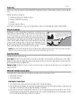
1.  Select as flat an area as possible near the aft end and center of boat where the hull is thin 

and not double. If the bottom has a runner down the center of boat, select an area to one side 
of the runner, but as close to the runner as possible. 

2.  Clean the inside of the boat with lacquer thinner in the area transducer is to be mounted. 

Outside of boat in this area should also be cleaned. (Not with lacquer thinner). 

3.  Put approximately one inch of water in the bottom of the boat. 
4.  Put transducer in the water. The bottom of the transducer should be in a flat area and should 

be in good contact with the bottom of the boat. 

5.  Operate the LCR with the boat operating at high speed. The transducer may have to be 

moved in order to find an area where satisfactory operation is observed. 

6.  When an area is found that produces satisfactory operation, mark the location of the 

transducer. 

Summary of Contents for TCR 101

Page 1: ......

Page 2: ...uding aluminum Please carefully consider the following before installing your transducer TRANSDUCER MOUNTING OPTIONS A Transom Mount The Humminbird high speed transducer allows the transducer element...

Page 3: ...bronz thru hull transducer has a threaded stem which installs through a hole drilled in the boat hull leaving the housing exposed under the boat This type of installation must be used for many boats...

Page 4: ...use a silicone sealant between the screwhead and bracket in order to prevent leaking See Figure C Step 2 BRACKET INSTALLATION Fiberglass Boats If your boat has a stepped transom located below and und...

Page 5: ...cally in the three slots found in the bracket It is important to use a silicone sealant between the screwhead and bracket in order to prevent leaking Step 3 TRANSDUCER PIVOT ASSEMBLY Assemble the pivo...

Page 6: ...the bracket Slide the O ring on to the headed pin and insert it through the two parts Assemble by screwing the x3 8 allen head screw into the end of the pin and tighten See Figure G Step 5 ANGLE ALLIG...

Page 7: ...h this type installation it is important that the transducer be mounted by someone familiar with the use of two part epoxy adhesives For this reason Techsonic Industries Inc will not be responsible fo...

Page 8: ...ye of the transducer The bubbles will disappear in a short time or can be removed by rubbing the transducer eye with your fingers while the transducer is in the water 4 If your instrument should fail...

Page 9: ...Install the mounting knobs and tighten snugly The unit can now be swiveled and tilted to any desired position...

Page 10: ...cket can also be mounted directly to the dash without the swivel mount however this method is not recommended since the unit cannot be rotated INSTALLING THE CABLES Your LCR comes equipped with Hummin...

Page 11: ...ole cover after determining the necessary wire length from the hole The power cable has a red lead to the positive post and the black lead to the negative post Install a 1 amp fuse between the red cab...

Page 12: ...ngbird s exclusive Total Screen Update instantly updates the entire TCR screen to include new information each time a function is changed no waiting for the changes to march onto the screen This featu...

Page 13: ......

Page 14: ...n the unit is turned off holding this button down for about 2 seconds activates the built in simulator Stop By pressing this button once you can stop or freeze the display Pressing the button once aga...

Page 15: ...tic setting from a range of 5 to 5 This level will maintain itself as long as you have the unit on automatically as a result of the TCR s Sensitivity Bias feature For example if you set the sensitivit...

Page 16: ...tomatically move up or down to stay on the bottom with the cursor showing you the protion of the total depth range that is being displayed This is an ideal feature for finding structure or locating fi...

Reviews: