


6
Note: It is important to remember that sonar cannot distinguish
between a fish and some other object suspended in the water.
Regardless of the object the sonar detects, it has the
possibility of being drawn as an arch.
Sonar Views (Deep Models Only)
The dual beam (50/200kHz) sonar information can be
displayed in several different views in the
C
HART
W
INDOW
. In the
200kHz view, only the sonar returns and
F
ISH
ID
from the
200kHz beam are displayed. Typically, the 200kHz
information provides greater bottom detail up to 800' and
works well while the boat is in motion. The 50kHz view only
shows the sonar returns and
F
ISH
ID
from the 50kHz beam.
The 50kHz information provides depth accuracy up to 2000'
and shows more targets in its wider beam. The Split Screen
view shows the 50kHz and 200kHz sonar information in
side-by-side windows on the display. The 200kHz/50kHz
view is a composite of the 200kHz sonar information and
the target information from the 50kHz sonar. See
CONTROL
PANELS
for details on selecting the sonar views.
CONTROL PANELS
Control Panels provide
access to important,
but infrequently-
adjusted features, such
as
C
HART
S
PEED
, M
ODE
, S
ONAR
V
IEW
, L
IGHT
, C
ONTRAST
, RTS W
INDOW
,
S
URFACE
C
LUTTER
, W
HITE
L
INE
, F
ILTER
,
D
EPTH
A
LARM
, T
EMP
A
LARM
, F
ISH
A
LARM
,
F
ISH
S
ENSITIVITY
, F
ISH
ID, S
IMULATOR
,
U
NITS
,
and, in International
Models only,
L
ANGUAGE
. Control
Panels allow you to set the
mode of operation as well
as additional features. Use
the
M
ODE
to change the
bottom tracking and depth
range method of display,
then use the other Control
Panels to add features to
your selected mode of
operation.
Note: Only the International Models (1005 and 1005 Deep)
contain a Language choice in the Control Panel, and only
the International Models support multiple units of measure,
such as fathoms and metres.
Note: The Sonar View, Fish ID, Fish Alarm, Fish Sensitivity, and
Filter choices only appear on the Deep Model Control Panels.
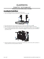
C
ONTROL
P
ANELS
are displayed by using the
C
ONTROL
P
ANEL
knob
and adjusted by using the
R
ANGE
knob. The active
C
ONTROL
P
ANEL
consists of three parts: the
C
ONTROL
P
ANEL
N
AME
,
S
ETTING
I
NDICATOR
, and
S
ETTING
R
EADOUT
.
The
C
ONTROL
P
ANEL
N
AME
indicates the feature, the
S
ETTING
I
NDICATOR
shows the current setting within the complete
range of adjustment, and the
S
ETTING
R
EADOUT
shows the
status when C
ONTROL
P
ANEL
is not selected.
To select a
C
ONTROL
P
ANEL
feature for adjustment, follow
these steps:
1. Press the
C
ONTROL
P
ANEL
knob
. A list of options appears
on the display. The option currently selected for
adjustment is indicated by a white background
color.
2. Rotate the
C
ONTROL
P
ANEL
knob
to select the desired
option for adjustment. Clockwise rotation selects
options higher in the list; counterclockwise rotation
selects options lower in the list.
Note: Not all options in the list can be viewed on the display at
one time. When the selected option is at the bottom of the list,
continue turning the knob to display other options.
3. Once the desired option is selected, turn the
R
ANGE
knob
to adjust. Adjustments are made immediately and are
shown by an indicator on the selected
C
ONTROL
P
ANEL
.
4. Remove the
C
ONTROL
P
ANELS
by pushing the
C
ONTROL
P
ANEL
knob
. Alternately, after a few seconds with no knob
press/turn activity, the
C
ONTROL
P
ANELS
are removed from
the display automatically.
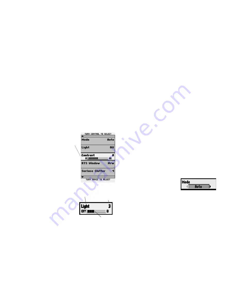
Mode
The first Control Panel to set
is Mode. Three modes of
operation control the
method used by the Legend 1000 Series to track the
bottom, select depth ranges and graph the
information on the LCD display. The Mode is selected
by changing the Control Panel setting to Auto,
Manual, or BTM Lock (Bottom Lock).
Automatic Mode
A
UTOMATIC
M
ODE
follows the bottom contour, changing
depth ranges as needed to keep the most recent sonar
returns visible on the display.
A
UTOMATIC
M
ODE
keeps the
acquired bottom visible at all times, showing sonar
returns from the surface to the bottom. This is done in
the top
²⁄₃
of the display to reduce range changes and
is useful when traveling across the water in areas
where the depth constantly changes.
USING THE LEGEND 1000 SERIES
SONAR VIEWS / CONTROL PANELS
Setting
Indicator
Active
Control
Panel
C
ONTROL
P
ANEL
Name
Setting
Readout