background image

Views

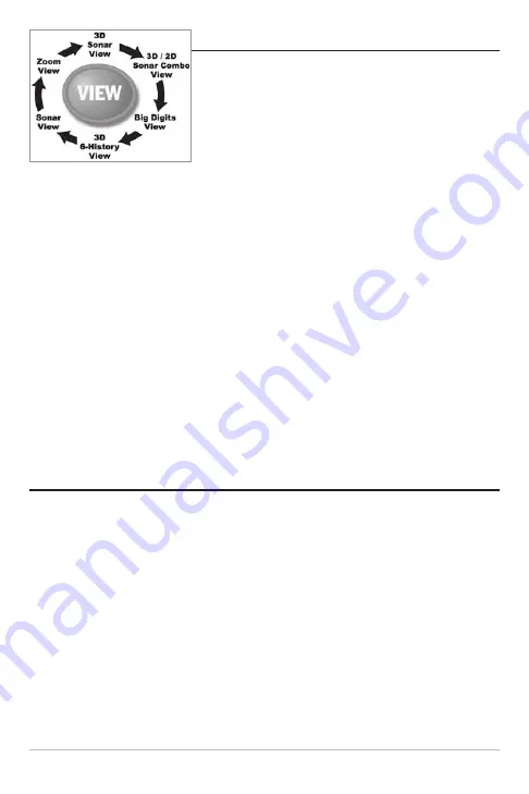
The views available on your Matrix® Fishing System are:

• 3D Sonar View
• 3D/2D Sonar Combo View 
• 6-Beam Sonar View
• 2D Sonar View
• 2D Zoom View
• 2D Big Digits View.

3D Sonar View

is the default view. When the VIEW key is pressed, the display cycles through

the available views.  When the EXIT key is pressed, the display cycles through the available
views in reverse order. Any view can be hidden or displayed as part of the view rotation using
the Views Menu tab. 

NOTE:

When you change any menu settings that affect the sonar, the view will update immediately

(i.e. you don’t have to exit the menu to apply the change to the screen). For instance, by switching
between "Inverse" and "Structure ID®" from the X-Press™ Menu it is possible to quickly alternate
between the two viewing methods.

NOTE: 

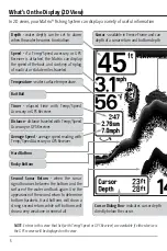
If the Depth number is flashing, it means that the unit is having trouble locating the bottom.

This usually happens if the water is too deep, the transducer is out of the water, the boat is moving
too fast, or for any other reason that the unit can’t accurately receive continuous data.  

3D Sonar View

3D Sonar View 

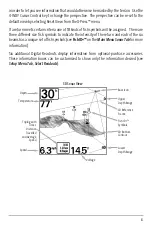
displays a 3-dimensional representation of the bottom.  Depth is always

displayed in the upper left hand corner.  Temperature and speed are displayed if the
temp/speed paddle wheel is connected or if a GPS receiver is connected.  The sonar returns
from each of the six elements are combined to create a 3-dimensional wire-frame
representation of the bottom.  The graphic depiction of the bottom provides you with an
effective tool for understanding the terrain beneath the boat. The boat symbol represents
the location of your boat in relation to the on-screen information.

The most recent sonar returns are charted on the upper right side of the screen and move to
the lower left as new information is received. The width of coverage is approximately equal
to the depth. Depth range is automatically selected to keep the bottom visible on the display.
In some situations, the selected point of view may prevent the display of some information
due to the slope of the terrain.  An option is available to change the perspective, or viewpoint,

7

Summary of Contents for 531338-1_C

Page 1: ...Matrix 47 Operations Manual Matrix 47 Operations Manual 531338 1_C ...

Page 2: ...incompliancewithknownandapplicableenvironmentalregulations andagoodneighborinthe communitieswherewemakeorsellourproducts WEEE DIRECTIVE EU Directive 2002 96 EC Waste of Electrical and Electronic Equipment Directive WEEE impacts most distributors sellers and manufacturers of consumer electronics in the European Union The WEEE Directive requires the producer of consumer electronics to take responsib...

Page 3: ...ew 11 Real Time Sonar RTS Window 12 2D Zoom View 13 2D Big Digits View 14 Bottom Presentation 15 Key Functions 17 POWER LIGHT Key 17 VIEW Key 17 MENU Key 17 4 WAY Cursor Control Key 18 EXIT Key 18 Accessory Bus 19 Powering Up the Unit 19 The Menu System 20 Start Up Options Menu 22 Normal Operation 22 Simulator 23 System Status 23 PC Connect with PC Connect Cable Only 24 Table of Contents ...

Page 4: ...D Sonar 2D Big Digits Views Only 29 Lower Range 2D Sonar 2D Zoom 2D Big Digits Views Only 30 Chart Speed 2D Sonar 2D Zoom 2D Big Digits Views Only 31 Bottom View 2D Sonar 2D Zoom 2D Big Digits Views Only 31 Zoom Level 2D Zoom View Only 32 Sonar Menu Tab 33 3D Bottom Style 34 3D Frame Style 34 Beam Select 34 Fish ID 35 Fish Sensitivity 36 Fish ID 3D Reference 36 Real Time Sonar RTS Window 37 Depth ...

Page 5: ...nsducer Attached 54 Display Problems 55 Finding the Cause of Noise 56 Matrix Fishing System Accessories 57 Specifications 58 Contact Humminbird 59 NOTE Entries in this Table of Contents which list International Only are only available on products sold outside of the US and Canada by our authorized International Distributors To obtain a list of authorized International Distributors please visit our...

Page 6: ...nsducer also receives reflected sound waves and converts them back into electrical signals for display on the sonar unit The transmit and receive cycle is very fast A sound wave can travel from the surface to a depthof240ft 70m andbackagaininlessthan ofasecond Itisunlikelythatyourboat can outrun this sonar signal A number of variables affect the nature of information which can be derived from the ...

Page 7: ...ontinuous series of these returned signals It then interprets this information to create a detailed 3 dimensional view of the terrain passing beneath your boat as you travel across the water 2D Sonar Your Matrix Fishing System also has the capability of displaying traditional 2 dimensional sonar information from either a 455 kHz beam or an 83 kHz beam The 455 kHz single beam has the advantageofpro...

Page 8: ...eed ifaTemp SpeedaccessoryorGPSReceiverisattached theMatrixcandisplaythespeed oftheboat andcankeepaTriplogofnauticalorstatutemilestraveled Bottom Contour Shows the shape of the bottom derived from depth measurements on6beams 3bottomstylesareavailable the front edges of the bottom contour are outlined to create a visual anchor The width ofthebottomcoveredisapproximatelyequal to the depth Timer elap...

Page 9: ...sh was found Left facing fish indicate fish off the port side of the boat while right facing fish indicate fish off the starboard side Each fish icon is available in three different sizes Larger fish icons are used to represent stronger returns The icons usedinthe2DSonarViewareidenticaltothe icons used in the 3D Sonar View Boat Direction Arrow A simple solid 3D boatisdrawnwhentheUpperDepthRangeis ...

Page 10: ...ess Hard bottoms will show a strong second return while soft bottoms will show a very weak one or none at all Hard Bottom Rocky Bottom Timer elapsed time with Temp Speed Accessory or GPS Receiver Distance distance traveled with Temp Speed AccessoryorGPSReceiver Average Speed average speed reading with Temp SpeedAccessoryorGPSReceiver Bait Ball Cursor available in Freeze Frame and can depth of a so...

Page 11: ...n three different sizes Larger fish icons are used to represent stronger returns The icons used in the 2D Sonar View are identical to the icons used in the 3D Sonar View RTS Real Time Sonar Window Soft Bottom Thermoclines layers of water with different temperatures that appear at different depths anddifferenttimesoftheyear Athermocline typically appears as a continuous band of many gray levels mov...

Page 12: ... the boat is moving too fast or for any other reason that the unit can t accurately receive continuous data 3D Sonar View 3D Sonar View displays a 3 dimensional representation of the bottom Depth is always displayed in the upper left hand corner Temperature and speed are displayed if the temp speed paddle wheel is connected or if a GPS receiver is connected The sonar returns from each of the six e...

Page 13: ...ymbols to indicate the intensity of the return and each of the six beamshasauniquesetoffishsymbols seeFishID ontheMainMenuSonarTabformore information Six additional Digital Readouts display information from optional purchase accessories These information boxes can be customized to show only the information desired see Setup Menu Tab Select Readouts 3D Sonar View Depth Upper Depth Range 3D Referenc...

Page 14: ...evaluating the bottom terrainfromthe3Dwindowwhilesimultaneouslyviewingthe2Dwindowforstructureand bottom hardness Refer to the 3D Sonar View and the 2D Sonar View sections for more information on these views The digital readouts in the 3D 2D Sonar Combo View cannot be customized making information such as water temperature and voltage unavailable in this view 3D 2D Sonar Combo View Depth 3D Sonar W...

Page 15: ...ides information on sonar targetsrelativetotheboat Thefarrightwindowdisplayssonartargetswhicharetothefar right of the boat and the far left window displays sonar targets which are to the far left of the boat The remaining windows display sonar targets which are successively closer to the boat The width of coverage is approximately equal to the current depth The digital readouts in the 6 Beam Sonar...

Page 16: ...henin2DSonarView yourunitoperateslikeatypicaldepthsounder Thereare however several exceptions The six beam 53 degree transducer allows you to search for fish with a much wider area of coverage Only the two center beams provide sonar returns for the bottomcontourshownonthedisplay Thefishsymbolsshowninthe2DSonarViewarethe same as those used in the 3D Sonar View providing information on the location ...

Page 17: ... through the use of grayscale The grayscale used matches the bottom view grayscale setting used in the sonar history window i e Inverse StructureID WhiteLine Bottom Black The depth of the sonar return is indicated by the vertical placement of the return on the display depthscale The Wide RTS Window indicates the sonar intensity through the use of a bar graph The length of the plotted return provid...

Page 18: ... range view Asthedepthchanges thezoomedviewupdatesautomaticallytodisplayamagnifiedimage ofthebottom TheZoomPreviewBoxshowswherethezoomedviewisinrelationtothefull range view The Zoom Level or magnification is displayed in the lower left corner and can be changed to suit conditions see Sonar X Press Menu Zoom Level Upper and Lower Zoom Depth Range numbers indicate the depth of the water you are view...

Page 19: ...ed to the system The Triplog shows distance traveled average speed and time elapsed since the Triplog was last reset The digital readouts in the 2D Big Digits View cannot be customized 2D Big Digits View Depth Temperature Speed Timer shows the time elapsed since Triplog was last reset Distance is the distance traveled since the Triplog was last reset Voltage the battery voltage Average Speed shows...

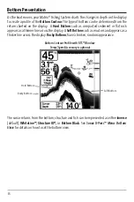
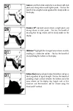
Page 20: ...ars as a thinner line across the display A Soft Bottom such as mud or sand appears as a thicker line across the display Rocky Bottoms have a broken random appearance The sonar returns from the bottom structure and fish can be represented as either Inverse default WhiteLine Structure ID or Bottom Black See Sonar X Press Menu Bottom View for details on how to set the bottom view Bottom Contour Profi...

Page 21: ...strong returns will be clearly visible on the display WhiteLine highlights the strongest sonar returns in white resulting in a distinctive outline This has the benefit of clearly defining the bottom on the display BottomBlackdisplaysallpixelsbelowthebottomcontouras black regardless of signal strength This has the benefit of providing a high contrast between the bottom and other sonar returns on th...

Page 22: ...ight and Contrast menu Use the 4 WAY Cursor key to select Light or Contrast and then use the LEFT or RIGHT Cursor key to change the settings Press EXIT to exit the Light and Contrast menu Press and hold the POWER LIGHT key for 3 seconds to turn the unit off A message will appear telling you how many seconds there are until shutdown occurs Your Fishing System should always be turned off using the P...

Page 23: ...EFT or RIGHT key to alter a menu setting 4 WAY Cursor Control Key The 4 WAY Cursor Control key has multiple functions depending on the situation Use the DOWN or UP arrow keys to select a menu choice from the menu list Use the LEFT or RIGHT arrow keys to change a menu setting Press any arrow key to activate Freeze Frame while in the 2D Sonar View and then use the 4 WAY Cursor Control key to positio...

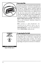
Page 24: ...x Fishing System Accessories in this manual as well as your accessory s Operations Manual for additional details NOTE Accessories to enable WeatherSense GPS Functionality and the SmartCast Wireless Sonar Link require separate purchases You can visit our website at www humminbird com or contact our Customer Resource Center at 1 800 633 1468 for additional details Powering Up the Unit Turn on your M...

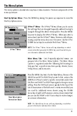
Page 25: ...vanced User Mode Main Menu Tabs Less frequently adjusted menus are grouped into the Main Menu System The Main Menu system is organized under the following tab headings to help you find a specific menu item quickly Alarms Sonar Setup Views and Accessories Press the MENU key twice for the Main Menu then use the 4 WAY Cursor LEFT or RIGHT key to select a tab and use the DOWN or UP key to select a spe...

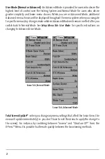
Page 26: ...ficmenus AnychangesmadewhileinAdvancedModewillremainineffectafteryou switch back to Normal Mode See Setup Menu Tab User Mode for specific instructions on changing to Advanced User Mode TotalScreenUpdate whenyouchangeanymenusettingsthataffecttheSonarView the view will update immediately i e you don t have to exit the menu to apply thechangeto the screen For instance by switching between Inverse and...

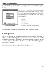
Page 27: ...Connect use with PC Connect Cable See the following paragraphs for more information about each of these choices Normal Operation Use Normal operation for on the water operation with a transducer connected In addition your Matrix Fishing System uses advanced transducer detection methods to determine if a transducer is connected If a functioning transducer is connected Normal operation will be selec...

Page 28: ...o letting your Matrix Fishing System enter Simulator automatically asitwillifatransducerisnotconnectedandyoudonothingduringpowerup Manually selecting Simulator from the Start Up Options menu allows you to pre configure your Matrix Fishing Systemforonthewateroperation Anymenuchangesyoumakewillbesavedforlateruse A message will appear on the display periodically to remind you that you are using the S...

Page 29: ...s powered up Exit System Status by powering your Matrix Fishing System off PC Connect With PC Connect Cable Only Use PC Connect to update the software of the Matrix control head This feature requires the use of the PC Connect Cable Complete instructions are included with the PC Connect Cable accessory NOTE The PC Connect Cable requires a separate purchase For more information visit our website at ...

Page 30: ... Sonar X Press Menu The Sonar X Press Menu provides access to the settings most frequently used Press the MENU key once while in any of the Sonar Views to access the Sonar X Press Menu Sonar X Press Menu ...

Page 31: ...Press Menu when you are in the 3D Sonar 3D 2D Sonar Combo or the 6 Beam Sonar View Automatic is the default setting When in automatic mode the lower range willbeadjustedbytheunittofollowthebottom Selectingaspecificsettinglocksthedepth range into Manual mode To adjust the 3D Lower Range 1 Highlight 3D Lower Range on the Sonar X Press Menu 2 Use the LEFT or RIGHT 4 WAY Cursor Control keys to increas...

Page 32: ...Menu 2 Use the LEFT or RIGHT 4 Way Cursor Control keys to increase or decrease the 3D History setting Most 2 9 Least Default 6 2D Sonar Window 3D 2D Sonar Combo View Only 2D Sonar Window sets the width of the 2 dimensional Sonar Window and is only available on the X Press Menu when you are in the 3D 2D Sonar Combo View To adjust the 2D Sonar Window 1 Highlight 2D Sonar Window on the Sonar X Press ...

Page 33: ...increase or decrease the 6 Beam Sensitivity setting Low 1 High 20 Default 10 Sensitivity 2D Sonar 2D Zoom 2D Big Digits Views Only Sensitivitycontrolshowmuchdetailisshownonthedisplay andisonlyavailableontheX Press Menuwhenyouareinthe2DSonar 2DZoom 2DBigDigitsViewsonly Increasingthesensitivity shows more sonar returns from small baitfish and suspended debris in the water however the display may bec...

Page 34: ...ual settings entered To adjust the Upper Range 1 Make sure you are in Advanced Mode then highlight Upper Range on the Sonar X Press Menu 2 Use the LEFT or RIGHT 4 WAY Cursor Control keys to increase or decrease the Upper Rangesetting 0to990feetor0to327meters InternationalModelsOnly Default 0 For example if you are only interested in the area between 20 and 50 feet deep you should set the Upper Dep...

Page 35: ...hen you start manually adjusting the Lower Range to indicate that you are in Manual mode NOTE A minimum distance of 10 feet will be maintained between the Upper and Lower Range regardless of the manual settings entered To adjust the Lower Range 1 Highlight Lower Range on the Sonar X Press Menu 2 Use the LEFT or RIGHT 4 WAY Cursor Control keys to increase or decrease the Lower Range setting AUTO 10...

Page 36: ...elects the method used to represent bottom and structure on the display and is only available on the X Press Menu when you are in the 2D Sonar 2D Zoom or 2D BigDigitsViews Inverserepresentsweakreturnsasdarkpixelsandstrongreturnsaslighter pixels Thishasthebenefitofensuringthatweaksignalswillbeclearlyvisibleonthedisplay StructureID representsweakreturnsaslightpixelsandstrongreturnsasdarkpixels This ...

Page 37: ... Zoom to increase the display resolution to separate sonar returns that are very close together To adjust the Zoom Level 1 Highlight Zoom Level on the Sonar X Press Menu 2 Use the LEFT or RIGHT 4 WAY Cursor Control keys to change the Zoom Level setting for the 2D Zoom View 2x 4x 6x 8x Default 2x NOTE The Zoom Preview Box tracks the bottom and cannot be moved by the user ...

Page 38: ...33 Sonar Menu Tab Press the MENU key twice to access the Main Menu System andthenpresstheRIGHT4 WAYCursorControlkeytoselect the Sonar tab Sonar Menu ...

Page 39: ... 3 4 Complex Default 3 Beam Select BeamSelectsetswhichsonarreturnsfromthetransducerwill be displayed on the screen When Beam Select is set to 455 kHz the returns from the 455 kHz narrow beams will be displayed in all views and the maximum depth capability of your unit will be 240 ft 75 m Whenthedepthisgreaterthan240ft 75m BeamSelectshouldbesetto83kHz Theunitwill continuetoacquiresonarreturnsbelow2...

Page 40: ...beams for a total of 18 possible fish symbols which can be displayed The following graphic illustrates the different Fish ID symbols and shows the beams with which they are associated For instance a hollow fish facing left indicates it was detected in the far left beam and a hollow fish facing right indicates it was detected in the far right beam When Fish ID is turned off the Fishing System shows...

Page 41: ...Matrix Fishing System to identify sonar returns as fish To change the Fish Sensitivity setting 1 Highlight Fish Sensitivity on the Sonar main menu 2 Use the LEFT or RIGHT 4 WAY Cursor Control keys to change the Fish Sensitivity setting Low 1 High 10 Default 5 Fish ID 3D Reference Fish ID 3D Reference selects the reference line style used in the 3D Sonar View Up draws a line from the fish icon to t...

Page 42: ...est rate possible and only displays returns that are within the transducer beam See Real Time Sonar RTS Window for additional detail To change the RTS Window setting 1 Highlight RTS Window on the Sonar main menu 2 Use the LEFT or RIGHT 4 WAY Cursor Control keys to change the RTS Window setting Wide Narrow Off Default Wide RTS Window Narrow RTS Window Off RTS Window Wide ...

Page 43: ... You can eitherturnDepthLinesOnorOff TheDepthLinesmenuchoiceisavailablewhenUserMode is set to Advanced see Setup Menu Tab User Mode To change the Depth Lines setting 1 Make sure you are in Advanced User Mode then highlight Depth Lines on the Sonar main menu 2 Use the LEFT or RIGHT 4 WAY Cursor Control keys to turn the Depth Lines setting On or Off Off On Default On Depth Lines Depth Lines ...

Page 44: ...oise Filter Advanced Noise Filter adjusts the sonar noise filter to limit interference on the display from sources such as your boat engine turbulence or other sonar devices The Noise Filter menu choice is available when User Mode is set to Advanced see Setup Menu Tab User Mode NOTE The Off setting removes all filtering Low Medium and High settings add progressive filtering of the sonar returns In...

Page 45: ...th on the Sonar main menu 2 UsetheLEFTorRIGHT4 WAYCursorControlkeystochangetheMaxDepthsetting AUTO 10 to 1000 feet 3 to 330 meters International Models Only Default AUTO Water Type Advanced Water Type configures your unit for operation in fresh or salt water The Water Type menu choiceisavailablewhenUserModeissettoAdvanced seeSetupMenuTab UserMode NOTE Insaltwater whatwouldbeconsideredalargefishmig...

Page 46: ...ss the Main Menu System The Alarms tab will be the default selection NOTE When an alarm is triggered you can silence it by pressing any key The alarm will be silenced and will not be triggered again until a new instance of the alarm condition is detected Alarms Menu ...

Page 47: ...h ID Alarm Fish ID Alarm sounds when your Matrix Fishing System detects fish that correspond to the alarm setting Fish ID Alarm will only sound if Fish ID is on To change the Fish ID Alarm setting 1 Highlight Fish ID Alarm on the Alarms main menu 2 Use the LEFT or RIGHT 4 WAY Cursor Control keys to change the Fish ID Alarm setting Off All Large Medium Large Default Off All Large Medium Large For e...

Page 48: ...ndbeforethebatteryvoltagedropstoolowforittobeusedtostart your main gasoline powered engine To change the Low Battery Alarm setting 1 Highlight Low Battery Alarm on the Alarms main menu 2 Use the LEFT or RIGHT 4 WAY Cursor Control keys to change the Low Battery Alarm setting Off 8 5V 13 5V Default Off Alarm Tone Alarm Tone selects the pitch of the alarm sound A brief tone willbeproducedasyouadjustt...

Page 49: ...44 Setup Menu Tab From any view press the MENU key twice to access the tabbed Main Menu System then press the RIGHT 4 WAY Cursor Control key until the Setup tab is selected Setup Menu ...

Page 50: ...menu 2 Use the LEFT or RIGHT 4 WAY Cursor Control keys to change the Units Temp setting Celsius Fahrenheit Default Celsius Units Distance with Temp Speed or GPS Receiver Units Distance selects the units of measure for all distance related readouts and will appear in the menu if a Temp Speed Accessory is connected and the paddlewheel has moved at least once or if a GPS Receiver is connected To chan...

Page 51: ...mph for Domestic models User Mode User Mode sets the menu system to either Normal or Advanced When set to Normal default setting only the basic menu options are shown WhensettoAdvanced additionalmenuchoicesareavailablethroughoutthemenusystem To change the User Mode setting 1 Highlight User Mode on the Setup main menu 2 Use the LEFT or RIGHT 4 WAY Cursor Control keys to change the User Mode setting...

Page 52: ...iplog on the Setup main menu 2 Use the RIGHT 4 WAY Cursor Control key to initiate Triplog Reset 3 The Confirm dialog box will appear To reset the Triplog press the RIGHT 4 WAYCursorControlkeyoncemore TocancelResetTriplog presstheLEFT4 WAY Cursor Control key Restore Defaults Restore Defaults resets ALL menu settings to their factory defaults Use this menu choice with caution To Restore Defaults 1 H...

Page 53: ...cedUserMode seeSetupMenuTab UserMode Data windows can display readouts from supported accessories such as Temp Speed Each data window can either be empty or contain one of the following Speed will be displayed if a Temp Speed Accessory is attached and the paddlewheel has moved at least once or if a GPS Receiver is connected Temperature Triplog willbedisplayedifaTemp SpeedAccessory is attached and ...

Page 54: ...key to initiate this procedure 3 TheSelectReadoutssubmenuwillappear showingalistofallReadouts UsetheUP or DOWN Cursor Control keys to select a particular Readout position then use the RIGHT orLEFTCursorControlkeystochangewhatwillbedisplayedatthatposition Off Speed Temperature Triplog Voltage Water Speed Default 2D Sonar View Customized 2D Sonar View ...

Page 55: ...Advanced TempOffsetwilladjustthetemperaturereadoutbytheamountentered Thismenuchoiceis available only when in Advanced User Mode see Setup Menu Tab User Mode To change the Temp Offset setting 1 MakesureyouareinAdvancedUserMode thenhighlightTempOffsetontheSetup main menu 2 Use the LEFT or RIGHT 4 WAY Cursor Control keys to change the Temp Offset setting 10 0 to 10 0 degrees Default 0 Speed Calibrati...

Page 56: ...Recommended Minimum Specific GNSS Data VTG Course Over Ground and Ground Speed ZDA Time and Date When navigating the following NMEA sentences are also output APB Autopilot Sentence B BWR Bearing and Distance to Waypoint RMB Recommended Minimum Navigation Info To turn NMEA Output on or off 1 Make sure you are in Advanced User Mode then highlight NMEA Output on the Setup main menu 2 UsetheLEFTorRIGH...

Page 57: ...the view rotation if it is set to Hidden and will be displayed in the view rotation if it is set to Visible The following views are available 2DSonarView 2DZoomView 2DBigDigitsView 3DSonarView 3D 2DSonarComboView 6 BeamSonarView SelfTest AccessoryTest To Change the View Status of Any View 1 Highlight the View main menu tab 2 Use the UP or DOWN 4 WAY Cursor Control keys to select a View 3 Use the L...

Page 58: ...oryisattached however additionalmenuchoicesthatsupport theaccessorywillbeaddedautomatically SeetheOperationsManualthatcomeswithyour accessory for detailed information NOTE Accessories to enable WeatherSense GPS Functionality and the SmartCast Wireless Sonar Link require separate purchases You can visit our website at www humminbird com or contact our Customer Resource Center at 1 800 633 1468 for ...

Page 59: ...ving corrosion from the battery terminals or wiring or actually replacing the battery if necessary Matrix Defaults to Simulator with a Transducer Attached A connected and functioning transducer will cause the newly started Matrix Fishing System to go into Normal operating mode automatically If when you power up your unit it goes into Simulator mode automatically even though a transducer is already...

Page 60: ...ted A mix of air and water flowing around the transducer cavitation may be interfering with the inter pretation of sonar data See your Installation Guide for suggestions on adjusting the transducer position Electrical noise from the boat s engine may be interfering with sonar reception See Finding the Cause of Noise for more information Sonar readings may be affected if the transducer is not posit...

Page 61: ...e re appears Todeterminewhethertheboat sengineisthesource of the noise increase the RPMs while the boat is in neutral and stationary to see if the noise increases proportionately if noise appears when you rev the engine the problem could be the spark plugs alternator or tachometer wiring Replace the spark plugswithresistorplugs installanalternatorfilter or route the control head power and transduc...

Page 62: ...ystem to access advanced FishingGPS trackplotter and navigation capabilities built in to yourMatrix FishingSystem GPS Connection Cable purchase the GPS Connection Cable in order to connect a handheld or other NMEA GPS compatible device that you may already own to your Matrix Fishing System WirelessSonarLink WSL purchasetheWirelessSonarLink WSL accessorytoreceiveremote sonar signals from a SmartCas...

Page 63: ...rating Frequency 455 kHz to 240 ft 75 m 83 kHz to 1000 ft 330 m 3D Area of Coverage 53 10 dB in 455 kHz 2D Area of Coverage 60 10 dB in 83 kHz 16 10 dB in 455 kHz Target Separation 2 Inches 63 5 mm Power Requirement 10 20 VDC LCD Matrix 640 V x 320 H Transducer SHS 7W Transducer Cable Length 20 ft 6 m Product specifications and features are subject to change without notice ...

Page 64: ...59 Notes ...

Page 65: ...60 Notes ...

Page 66: ...ays By Telephone Monday Friday 8 00 a m to 4 30 p m Central Standard Time 1 800 633 1468 By e mail typically we respond to your e mail within three business days cservice johnsonoutdoors com For direct shipping our address is Humminbird Service Department 678 Humminbird Lane Eufaula AL 36027 USA ...

Reviews: