background image

http://www.huidu.cn/

5

Chapter 2 Panel

1.

Rear panel

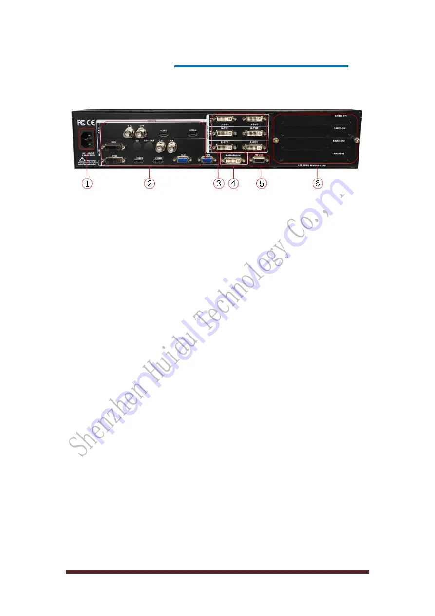
Page 1—Video processor rear panel

AC power input

Connect to the video processor using an IEC standard power

cord with an input power of 100-240 VAC, 50-60 Hz.

Video input

Input standard for each interface.

CV1

CV2

CV3

CV4 Composite video input

With the BNC interface, the input

video supports PAL, PAL-M/N, NTSC, and SECAM formats. You can connect a

DVD player, a video camera, etc.

DVI1, DVI2

digital video input, using DVI-I standard interface, can use DVI-I or

DVI-D cable, video input format supports VESA standard.

HDMI1, HDMI2, HDMI3, HDMI4 HD video input, using HDMI-A standard

interface, input video supports HDMI1.3 standard and VESA standard. Commonly

used to connect desktop computers and HDMI HD players.

VGA1, VGA2 video input, using DB-25 standard interface, input video supports

VESA standard, used to connect desktop computer, notebook or other VGA video

output device.

SDI digital video input, SDI-LOOP, SDI signal loop out, use BNC interface, input

video supports HD camera.

Video output

Processor programming video output interface

● DVI video output, using DVI-I connector, the output video format is set by the

processor, three groups of CH-A, CH-B, CH-C simultaneously output the same signal.

Often used to connect to an LED send card or monitor.

CH-M/Monitor output, using DVI-I connector, output video is connected to the

display, as a display user's real-time operation image position and switching effects.

RS-232 — Serial communication connector for engineering test, program burning,

PC software control, communication baud rate is 115200bps.

LED Sending Card — The reserved LED sending card installation location allows

for the installation of 4 sending Cards. When installing, the user can first disassemble

the back cover and the small cover, and install and fix it. There are 6 5V power

connectors and 2.0x4 PIN connectors inside. Plug in the 5V power supply after

installation.

Summary of Contents for HDP902

Page 1: ...http www huidu cn 1 Operation instruction Video processor splicer HDP902 V1 0 20190903...

Page 2: ...e product This equipment is intended to be used with a main power system with a grounded neutral conductor The third grounding pin is a safety feature do not attempt to bypass or disable it Power disc...

Page 3: ...ration menu Default menu Main menu Setting and Operation Language Reset Output Resolution Switching Effect Fade time settings Black and Freeze settings Splicing applications Equal Splicing Left and ri...

Page 4: ...ng 2 channels of DVI 4 channels of HDMI 2 channels of VGA 4 channels of CVBS 1 channel of 3G SDI SDI LOOP optional Each channel can receive standard resolution or high resolution video signals DVI and...

Page 5: ...sktop computer notebook or other VGA video output device SDI digital video input SDI LOOP SDI signal loop out use BNC interface input video supports HD camera Video output Processor programming video...

Page 6: ...NPUT button area all 13 channels of input switching keys test patterns and VGA auto correction function keys are included The button indicators in the keypad have three states namely The button indica...

Page 7: ...ching button The HDMI3 and HDMI4 buttons correspond to the HDMI3 and HDMI4 video input interfaces on the rear panel The MAIN button is the main channel button and the A C channel input defaults to the...

Page 8: ...PIP shortcut key to quickly turn the PIP function on or off The use of PIP is described in detail in the following sections Tip When the PIP Picture in Picture function is active the CUT function and...

Page 9: ...sreen image Features system Main function description Set the output resolution and fine tune the output Adjust aliquot stitching unequal splicing or partial image display Set the size position and i...

Page 10: ...c showing the processor menu system The main parameters All input selection keys and function keys are available in the default menu Input source Features Input M HDMI 1920x1080 60 preset 1 Input A HD...

Page 11: ...ut resolution and precise adjustment of the resolution 1 First select a resolution larger than the display Default Menu Main Menu Output Monitor Output A Output B Output C Output Resolution Common Res...

Page 12: ...Tip Before setting the splicing parameters first confirm whether the output A output B output C channel resolution is set 6 Level 1 picture 3 stitching take the total number of images 3840X1152 60Hz...

Page 13: ...otal Pixels 1920 Default menu Main Menu Splicing Splicing A Parameter Setting Horizontal Start 0 Default menu Main Menu Splicing Splicing A Parameter Setting Vertical Start 0 Output B channel stitchin...

Page 14: ...icing parameters equivalent to intercepting part of the screen parameters and the total pixel value and the starting value are adjusted by visual inspection Default menu main menu function partial fun...

Page 15: ...ut signal source cannot realize the picture in picture function so the user can refer to the picture in picture input source conflict table in the table below Default menu main menu multiple screen pi...

Page 16: ...input channel and FIG 11C is a cutout effect Page11A PPT for picture in picture channel 11B Main input channel diagram 11C Keying effect The setup steps in the main menu Default menu main menu multipl...

Page 17: ...hen switching to a VGA input source the processor automatically corrects the color image size and position of the input source If the processor does not have automatic correction successful the user c...

Reviews: