


16
INSTALLING THE MOUNT ON A WOOD FRAMED ROOF
INSTALLATION INSTRUCTIONS
Before you begin, make sure the rafters or trusses (called mem-
bers) in your house are located 16 to 24 inches on center.
Remember that 2 x 4 and 2 x 6 inch members are actually
1-1/2 inches thick.
Note: for an installation to be successful, the mast must be plumb. Re-
plumb the mast whenever instructed to do so, and re-plumb it when-
ever you feel it is necessary.
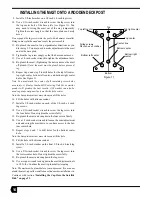
1. Orient the universal mount so the square hole in the base
plate is at the top as in Figure 13 before installation.
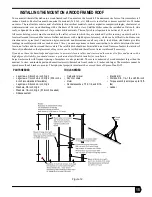
2. Use a 1/2-inch socket wrench to loosen the adjustment nuts
and swing the mast so that it is oriented as in Figure 14.
3. Mark the centerline of the rafter or truss.
.
DANGER
• If the satellite dish contacts electric power lines, you
will be killed or seriously injured.
• Before starting the installation procedure, make sure
there are no power lines nearby.
CAUTION
• Rafters or trusses must be located 16 to 24 inches
apart on center, except for large-timber roofs, which
can be located no more than 24 inches apart on cen-
ter.
• The roof surface must consist of relatively thin, resilient
materials, such as asphalt or composite shingles,
sheet metal, or similar materials, over wood sheathing
with a thickness that must not exceed 3/4 inch.
• Satellite dishes cannot be installed on slate roofs or
Spanish tile roofing made of clay or other brittle materi-
als.
• The roof pitch (also called slope) must be between
3:12 and 12:12.
• The satellite dish cannot be installed on a flat roof.
• Center hole lag screws
must
be centered in the rafter
or truss.
• The satellite dish should not be installed on a wood
frame roof unless the interior is unfinished so that
placement of lag screws can be verified and the roof
reinforced if necessary.
• Install the satellite dish only as described in this man-
ual.
CAUTION
If you do not have the knowledge and experience to
accurately locate rafters and the center of rafters with a
high degree of reliability, you should contact a professional
satellite dish installer for installation.
Figure 13
Figure 14
Corner holes
Corner holes
Top center hole
Bottom center hole
Centerline
Rafter or truss
Center hole lag
screws are 3/8 inches
by 4 inches
Corner lag screws
are 3/8 inches
by 2 inches
Mast
(top view)
Level
Mast
Plumb vial
Adjustment nut
(2 places)
Pivot bolt
Bubble must
be centered
between
marks
Carpenter's level
Bubble
T00
Summary of Contents for DW 3000 One-Way
Page 4: ...iv ...