Chapter 3 • Assembling the antenna
1037312-0001 Revision B
27
Tightening the hardware
Tighten the hardware as follows:
1. Tighten the three nuts on the reflector rim (indicated by the
black arrows in Figure 19).
2. Tighten the nut where the support rods attach to the feed
support arm (indicated by the white arrow in Figure 19).
The antenna is now assembled, as shown in Figure 20, and ready
for installation of the radio assembly.
•
If you are installing a J-type radio, go to
Chapter 4 – Installing a J-type radio assembly, on page 31.
•
If you are installing a cradle-type radio, go to Chapter 5 –
Installing a cradle-type radio assembly, on page 43.
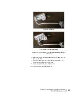
Figure 19: Tightening nuts on support rods and feed support arm
Figure 20: Completed antenna assembly (without radio)
Summary of Contents for AN6-098P
Page 6: ... Contents vi 1037312 0001 Revision B ...
Page 10: ... Tables x 1037312 0001 Revision B ...
Page 22: ...Chapter 1 Overview 6 1037312 0001 Revision B ...
Page 46: ...Chapter 3 Assembling the antenna 30 1037312 0001 Revision B ...
Page 58: ...Chapter 4 Installing a J type radio assembly 42 1037312 0001 Revision B ...
Page 72: ...Chapter 6 Cabling and connections 56 1037312 0001 Revision B ...
Page 92: ...Chapter 7 Pointing the antenna 76 1037312 0001 Revision B ...
Page 94: ... Acronyms and abbreviations 78 1037312 0001 Revision B ...


