


212
Series Tooling Alcoa Fastening Systems
17
D
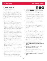
ISASSEMBLY
See applicable illustrations.
For parts identification, refer to applicable fig-
ures, tables and parts lists. Numbers in paren-
theses ( ) are reference numbers shown in man-
ual.
The following procedure is for complete disas-
sembly of tool. Disassemble
ONLY
those compo-
nents necessary to replace damaged or worn O-
rings, QUAD rings, back-up rings and other com-
ponents.
1. Disconnect tool from air source.
2. Unscrew Retaining Nut (2) and remove Nose
Assembly. Remove Pintail Tube (1).
3. Unscrew Bleed Plug (4) including O-ring (5)
from top of Handle/Head (3). Turn tool over
and allow fluid to drain into container - - tool
may be cycled to clear tool more completely.
Discard fluid.
4. Pull Deflector (17) off End Cap (14).
5. Using wrench, unscrew End Cap (14). Slide
out Spring (13)
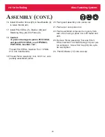
6.
CAUTION - - to prevent damage to Piston
Seals and Gland Seals when removing
them - - install
OPTIONAL
POLY-SEAL
Insertion Tool (121694-212).
Thread POLY-SEAL Insertion Tool, 121694-
212, into head/handle.
7. Slide Spacer, 123112-2, over piston rod.
8. Thread Piston Assembly Tool, 123111-2, onto
piston.
9. Push complete piston from front using brass
drift - -allow clearance for
piston as it exits tool.
10.Remove Piston Assembly Tool, Spacer, and
POLY-SEAL Insertion Tool.
11.Inspect Piston (6) for wear, scoring or dam-
age. Replace when necessary. Remove
Retaining Ring (64) and Washer (63). Hold
tool securely with bottom up.
12. Remove three Button Head Screws (51) with
1/8 hex key. Remove Muffler End Cap (50)
and Bottom Exhaust Gasket (48). Remove
Muffler (47) with O-ring (46) from end cap.
13. Remove Retaining Ring (45) from Cylinder
(24).
14. Screw Button Head Screws (51) back into
Cylinder Head (43). Carefully pull on
screws to remove Cylinder Head (43).
!
!
WARNING
Be sure air hose is disconnected before
cleaning or when replacing worn or
damaged tool components. Tool may
be actuated if not disconnected and
cylinder is under pressure. Severe
personal injury may result.
WARNING
Never cycle tool without bleed plug
installed and tightened, the bottle
installed and tightened in tool head, or
the fillport held over a suitable con-
tainer.
If fluid is present it will spray
out of tool. Severe eye injury may
result.
Air pressure MUST be set at 20
- 40 psi.
Summary of Contents for ALCOA 212
Page 1: ...11 09 2009 HK838 INSTRUCTION MANUAL 212 PNEUDRAULIC INSTALLATION TOOL...
Page 2: ......
Page 4: ...This page is intentionally blank...
Page 8: ...212 Series Tooling Alcoa Fastening Systems 6 Fig 1 Outline Drawing...
Page 23: ...212 Series Tooling Alcoa Fastening Systems 21 Fig 5 Handle Assembly...
Page 25: ...212 Series Tooling Alcoa Fastening Systems 23 Fig 10 Piston and Gland Removal...
Page 26: ...212 Series Tooling Alcoa Fastening Systems 24 Fig 11 Piston and Gland Insertion assembly...
Page 27: ...212 Series Tooling Alcoa Fastening Systems 25 Fig 12 Gland Assembly...
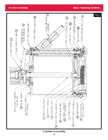
Page 28: ...212 Series Tooling Alcoa Fastening Systems 26 Fig 13 Cylinder Assembly...