


212
Series Tooling Alcoa Fastening Systems
16
T
ROUBLESHOOTING
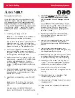
Always check out the simplest possible cause of
a malfunction first. For example, an air hose not
connected. Then proceed logically, eliminating
each possible cause until the defective part is
located. Where possible, substitute known good
parts for suspected bad parts. Use this page as
an aid in locating and correcting malfunction:
S
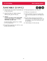
PARE PARTS AND SERVICE KIT
The quantity of spare parts that should be kept
on hand varies with application and number of
tools in service. Service parts kit containing per-
ishable parts such as O-rings, back-up rings,
etc., should be kept on hand. Parts included in
SERVICE KIT 212KIT
, are indicated by asterisks
(*) in
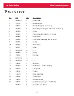
PARTS LIST
.
1. Tool fails to operate when trigger is depressed.
a. Throttle valve O-ring (53) or O-ring (54) worn or damaged.
b. Broken throttle cable.
2. Tool does not complete fastener installation or break pintail.
a. Air pressure too low. Set to 90 psi.
b. Hydraulic fluid low causing short stroke.
c. Air piston QUAD Ring (40) worn or damaged.
d. Air in hydraulic system (see
FILLING AND BLEEDING TOOL
).
3. Hydraulic fluid exhausts with air.
a. Worn or damaged O-ring (37) and Back-up Ring (36) or
O-ring (30); O-ring (33) and Back-up Ring (34); POLY-SEAL
(32) or QUAD Ring (31).
4. Hydraulic fluid leaks at Hydraulic Cylinder Head (14).
a. Worn or damaged Pull Piston Rod POLY-SEAL (7).
5. Hydraulic fluid leaks at Pull Piston Rod (6).
a. Worn or damaged Pull Piston Rod POLY-SEAL (7).
6. Pull Piston (6) will not return.
a. Broken or weak Spring (13).
7. Air leaks at air Cylinder Head (43).
a. O-ring (44) damaged.
Summary of Contents for ALCOA 212
Page 1: ...11 09 2009 HK838 INSTRUCTION MANUAL 212 PNEUDRAULIC INSTALLATION TOOL...
Page 2: ......
Page 4: ...This page is intentionally blank...
Page 8: ...212 Series Tooling Alcoa Fastening Systems 6 Fig 1 Outline Drawing...
Page 23: ...212 Series Tooling Alcoa Fastening Systems 21 Fig 5 Handle Assembly...
Page 25: ...212 Series Tooling Alcoa Fastening Systems 23 Fig 10 Piston and Gland Removal...
Page 26: ...212 Series Tooling Alcoa Fastening Systems 24 Fig 11 Piston and Gland Insertion assembly...
Page 27: ...212 Series Tooling Alcoa Fastening Systems 25 Fig 12 Gland Assembly...
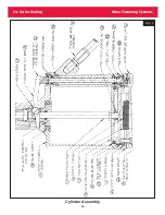
Page 28: ...212 Series Tooling Alcoa Fastening Systems 26 Fig 13 Cylinder Assembly...