Huck 256BT Instruction Manual Download Page 12

256BT Pneudraulic Installation Tool 

(HK1109)

Alcoa Fastening Systems

12

Equipment Required:

- Shop airline with 90 - 100 psi max.
- Air regulator
- Fill bottle, 120337, (supplied with tool).
- Large flat blade screwdriver
- Optional Stall Nut 120824
- Nose assembly
- Fasteners (Optional)

Preparation:

1. Install air regulator in

airline and set pressure to
20-40 psi.

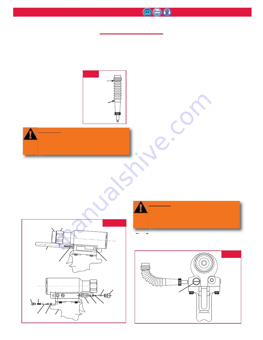
2.  Fill bleed bottle almost full

of DEXRON III - ATF or
equivalent. (Fig.6)

Refill tool only when red line on plunger drops below the
red line on the reservoir housing or when tool is rebuilt.

USE:  AUTOMATIC TRANSMISSION FLUID DEXRON
III, OR EQUIVALENT.

Step 1

Screw Fill Tool into Reservoir Plunger, pull Plunger into
Housing and lock Fill Tool in full forward position by
tilting handle (long side touching tool) and locking in
place. (Fig. 7)

Step 2

Remove Plugs (57) and (50) and all guides, springs and
balls from ports in head.  Reinstall Plug (57) in head in
Relief Valve port (front of tool). (Fig. 7 & 8).

Step 3

Screw retaining nut onto head assembly. Screw Stall
Nut (optional see note:) onto Piston and tighten to
ensure full thread engagement. Back off retaining nut
until it engages stall nut.  Check Piston location.  Piston
must be all the way forward and locked with stall nut
and retaining nut. 

Note:

If Stall Nut is not used, piston

must be pushed to the full forward position before
installing valves.

Step 4

Attach the tool air source momentarily to seat air piston
at bottom of cylinder. Disconnect tool.  With fill port
facing up, (check valve on side) lay tool on its side. 

Step 5

Install fill bottle in head fill port (check valve hole). 
(Fig. 7 & 8)

Step 6

Connect tool to shop air regulated to 20 to 40 psi.  Cycle
tool 20-30 times. Watch for air bubbles escaping from
the tool into bottle.  (You may rock the tool to free
trapped air in the tool.)  Do not allow the air to re-enter
the tool.

Step 7

When air bubbles no longer appear in bottle, remove fill
bottle while tool is lying on its side.

Stall Nut

120824

8

HUCK

U.S. PAT. 4597263

256/257

57

56

54

53

55

50

44 43

45

1

Fill Tool

Red Line

Indicator

33

FIG.  7

FILL

POINT

120337

Fill Bottle

Assembly

FIG.  6

57

FIG.  8

WARNING: Avoid contact with hydraulic
fluid.  Hydraulic fluid must be disposed of
in accordance with Federal, State and Local
Regulations.  Please see MSDS for
Hydraulic fluid shipped with tool.

WARNING: Air pressure MUST be set to 20
to 40 psi to prevent possible injury from
high pressure spray.  If plug (50) is
removed, fill bottle must be in place before
cycling tool.

F

F

ILL

ILL


AND

AND

 B

 B

LEED

LEED

Summary of Contents for 256BT

Page 1: ...07 10 2013 HK1109 INSTRUCTION MANUAL 256BT PNEUDRAULIC INSTALLATION TOOL...

Page 2: ...256BT Pneudraulic Installation Tool HK1109 Alcoa Fastening Systems 2...

Page 3: ...s 3 SAFETY 4 SPECIFICATIONS 5 PRINCIPLE OF OPERATION 6 OPERATING INSTRUCTIONS 6 MAINTENANCE 7 DISASSEMBLY 8 9 ASSEMBLY 10 11 FILL AND BLEED 12 13 ASSEMBLY DRAWINGS 14 15 PARTS LIST 15 16 MEASURING TOO...

Page 4: ...uitable postures as it is likely for these not to allow counteracting of normal or unexpected tool movement 8 If the assembly power tool is fixed to a suspension device make sure that fixation is secu...

Page 5: ...also be used and is required to comply with OSHA regulation 1926 302 paragraph d the fluid used in hydraulic power tools shall be fire resistant fluid approved under schedule 30 of the US Bureau of Mi...

Page 6: ...aining from qualified personnel Do not bend tool to free if stuck Tool should only be used to install fasteners NEVER use as a jack spreader or hammer BOBTAIL Fastener Installation Place pin in workpi...

Page 7: ...2 Bleed the air line to clear it of accumulated dirt or water before connecting air hose to the tool 3 Check all hoses and couplings for damage or air leaks tighten or replace if necessary 4 Check the...

Page 8: ...is damaged contact your Huck representative If Seat 52a is damaged it can be removed by using the following procedure NOTE If seat is taken out it cannot be reused it must be replaced Figure 9 10 Seat...

Page 9: ...et and extension and with 7 64 hex key remove piston Screw 30b Fig 4 9 22 Return cylinder and handle to upside down position and secure in a vise 23 Grip Self locking Nut 19 under Air Piston 26 with p...

Page 10: ...r 21 on center of Cylinder Assy 25 Place Gasket 23 on Cylinder Assembly 28 NOTE Lip must face Muffler End Cap 20 Place Muffler End Cap 20 on top of Gasket 23 and secure with 3 Button Head Screws 18 us...

Page 11: ...44 Spring 45 and Plug 50 into head 18 Push Pintail Deflector 14 onto barbed end of Pull Piston 11a Fig 9 19 Place O rings 33b on Bleed Plugs 33a and screw assemblies into Handle Qty 1 and Cylinder He...

Page 12: ...ion Piston must be all the way forward and locked with stall nut and retaining nut Note If Stall Nut is not used piston must be pushed to the full forward position before installing valves Step 4 Atta...

Page 13: ...ion Lay tool on its side with the reservoir on the high side and remove Bleed Plug 33 from the reservoir side Top off reservoir by placing a few drops of oil in hole and wait for air bubbles to escape...

Page 14: ...turn Gland Assy 15b 15e 15a 15c 15d 31 Pull Gland Assy 31c 31b 31e 31d 31a 30 Piston Assy 30a 30e 30b 30c 30d 2 16 17a 17c 17d 25a 26b 26a 4 5 2 3 1 8 7 12 10 11 13 14 9a SECTION A A 48 47 57 52c 52b...

Page 15: ...Gland n a 1 12b O Ring 505887 1 12c Back up Ring 501118 1 12d Polyseal 508428 1 13 Cylinder Cap 129550 1 14 Wiper 505894 1 15 Return Gland Assy contains 112502 1 15a Return Gland n a 1 15b O Ring 500...

Page 16: ...14530 1 When replacing these parts the assembly must be ordered They are not sold separately Item Description Part No Qty 21 Muffler 115554 1 22 O Ring 500777 1 23 Gasket 126941 3 1 24 Retaining Ring...

Page 17: ...TROKE DISTANCE A DISTANCE B FIG 11 1 With the Piston in the fully forward position measure DISTANCE A from face of the Cylinder to the face of the Piston 2 Cycle tool and keep Piston in the full rear...

Page 18: ...assembly b Check for loose Retaining Nut c Check for piston drift 4 Tool has piston drift a Loose collet crashing into the front of the anvil causing the relief valve to open allowing the piston to dr...

Page 19: ...nety 90 day warranty period for tooling other items nonstandard or custom products described above and Huck shall inspect products for which such claim is made TOOLING PART S AND OTHER ITEMS NOT MANUF...

Page 20: ...ganization Alcoa Fastening Systems AFS maintains company offices throughout the United States and Canada with subsidiary offices in many other countries Authorized AFS distributors are also located in...

Reviews: