background image


ELECTRIC RANDOM-ORBITAL 

SANDER 

EN


11 


- Voltage and power frequency must match the data displayed on the identification plate. Make sure that tool is 
switched off before plug is connected. 


REMOVING AND MOUNTING THE BACKING PAD 

 
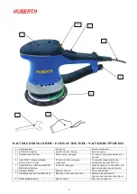
- Use the spanner wrench (6) to unscrew the back-up pad bolt; 
- Reverse the procedure when fitting the disc pad (5). 
 

FITTING ABRASIVE PAPER DISCS 

 
Press the abrasive disc into the pad ensuring that the holes in the abrasive paper coincide with extraction holes in the disc pad. 
 

BEFORE STARTING THE TOOL 

 
Ensure that: 
- the speed control (8) is in MAX position; 
- the start button (2) is working properly; 
- all the components of the tool are mounted correctly and do not show any signs of damage; 
- the tool must be connected to a suitable and efficient aspiration device (mobile suction unit or dust bag). 
 

STARTING AND STOPPING 

 
- Starting: push the button (2) forward towards the body of the tool. 
- Stopping: release the control button (2). 
 

TEST RUN 

 
Start the tool and check that there are no unusual vibrations, no mismatching of the abrasive paper disc. Otherwise switch-off 
the tool immediately and eliminate the cause. 
 

SELECTING THE RPM 

 
The  RPM  can  be  adjusted  by  using  the  speed  control  (8)  from  MAX  to  MIN.  The  choice  of  speed  depends  on  the 
characteristics of the abrasive paper disc and the material to be worked. 

 
REPLACING THE ABRASIVE PAPER DISCS 

 
- Used discs can be removed by simply tearing them off; 
-  New  Velcro  discs  are  mounted  by  simply  pressing  them  into  the  backing  pad,  making  sure  that  the  holes  cut  in  the  disc 
coincide with those in the backing pad. 
 

USABLE DISCS 

 
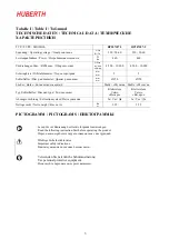
Ø150 mm Velcro backed abrasive paper discs with dust extraction holes. 
 

MAINTENANCE 

 
All maintenance operations are carried out with the power supply disconnected. 
At the end of each work session, or when required, remove any dust from the body of the tool using a jet of compressed air, 
paying particular attention to the motor ventilation slots. 

 
No other maintenance operations must be undertaken by the user

Maintenance and cleaning of the inner parts, like brushes, ball bearings, gears etc. or others, must be carried out only by an 
authorized customer-service workshop. 


Summary of Contents for RP207187-3

Page 1: ...1 DE BETRIEBSANLEITUNG 4 EN USER S MANUAL 9 RU 13...

Page 2: ...r Power cable with plug 4 Anschlu f Absaugschlauch Innenweite 29 mm 29 mm int suction pipe connection 29 5 Schleifteller m Klettverschlu f r Haftschleifscheiben Velcro backing pad 6 Zapfenschl ssel Sp...

Page 3: ...c pad diameter mm 150 150 L cher Holes Multy Multy Typ Schleifteller Disc pad type Klettsystem Velcro Klettsystem Velcro Absaugvorrichtung Extraction system Ja Yes Ja Yes Nettogewicht Netto weight Kg...

Page 4: ...vermindert das Risiko eines elektrischen Schlages 3 SICHERHEIT VON PERSONEN a Seien Sie aufmerksam achten Sie darauf was Sie tun und gehen Sie mit Vernunft an die Arbeit mit einem Elektrowerkzeug Benu...

Page 5: ...den Sicherheitsvorkehrungen vermeiden a Das Werkzeug stets fest greifen und den eigenen K rper und die Arme in eine Position bringen in der Sie dem R ckschlag standhalten k nnen Stets den zus tzlichen...

Page 6: ...er Andr cken auflegen Dabei darauf achten da die L cher in der Schleifpapierscheibe ber den Absau g ffnungen im Schleifteller liegen VOR DER INBETRIEBNAHME Stellen Sie folgende Sicher der Drehzahlregl...

Page 7: ...ist Im Fall einer nachweislichen Funktiosst runa mu das Ger t dem Hersteller komplett montiert originaTverpackt und mit beiliegender Garantiekarte fracht und portofrei bergeben bzw zugesendet werden D...

Page 8: ...orfen oder im Hausm ll entsorgt werden sondern muss bei den autorisierten Zentren zur Abfalltrennung abgegeben werden wenden Sie sich an die zust ndigen Beh rden vor Ort um zu erfahren wo das Produkt...

Page 9: ...skid safety shoes hard hat or hearing protection used for appropriate conditions will reduce personal injuries c Prevent unintentional starting Ensure the switch is in the off position before connecti...

Page 10: ...nt at the point of snagging d Use special care when working corners sharp edges etc Avoid bouncing and snagging the accessory Corners sharp edges or bouncing have a tendency to snag the rotating acces...

Page 11: ...hat there are no unusual vibrations no mismatching of the abrasive paper disc Otherwise switch off the tool immediately and eliminate the cause SELECTING THE RPM The RPM can be adjusted by using the s...

Page 12: ...our responsibility that the hand held non electric power tool which is mentioned in the present operating manual conforms to the Essential Requirements of Safety of the following Directive 2006 42 CE...

Page 13: ...RU 13 1 2 3 3 4...

Page 14: ...RU 14 5 8 12 1 102 7...

Page 15: ...RU 15 6 5 8 2 2 8...

Page 16: ...RU 16 150 UNI EN 28662 UNI EN ISO 5349 2 5 2 12 2006 42 CE Ma EN ISO 12100 1 2003 EN ISO 12100 2 2003 UNI EN 983 2009...

Page 17: ...RU 17 ISO 14121 1 2007 UNI EN ISO 3744 1997 A UNI EN ISO 11203 1997 UNI EN ISO 5349 1 2004 WEEE 2002 96 CE WEEE 2003 108 CE...

Page 18: ...OL AND THE PURCHASE INVOICE IN CASE OF GUARANTEE REPAIR RU DE Eine eventuelle garantieleistung ist nur m glich wenn diese garantiekarte vollst ndig ausgef llt ist EN After the complete fill in of this...

Reviews: