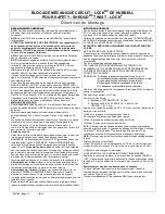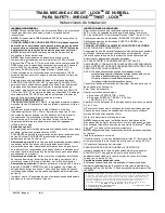
HUBBELL CIRCUIT - LOCK™
SAFETY-SHROUD TWIST LOCK
®
MECHANICAL INTERLOCK
WIRING INSTRUCTIONS
(Continued)
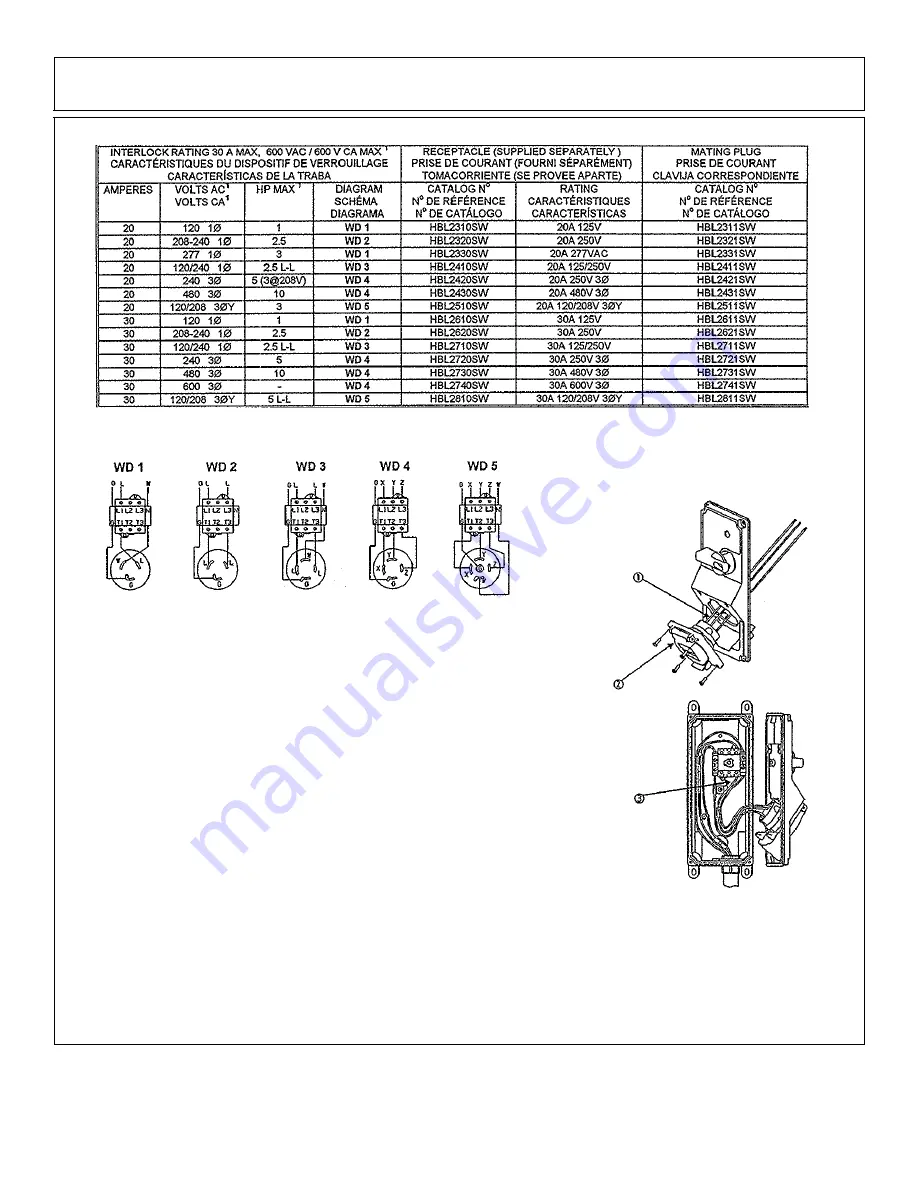
Select the proper wiring diagram.
¹VOLTAGE (AC ONLY) AND HORSEPOWER RATINGS ARE DETERMINED BY THE SWITCH BUT MAY BE LIMITED BY THE
AMPERE RATING OF THE RECEPTACLE.
NOTE: “G” designates grounding wire (bare, green or green with yellow stripe) and yellow and green
grounding buss.
“N” designates the blue neutral (grounded) buss.
“W” designates the white neutral (grounded) wire.
Wire the line-side of the switch, grounding buss, and neutral buss (if required).
Strip conductor insulation ½ inch (13mm).
Tighten the terminal screws:
a)
SWITCH terminals 12 pound
·
inches (1.4N
·
m)
b)
GROUND 16-18 pound
·
inches (1.8-2.0N
·
m); and NEUTRAL 13-15 lb.-in. (1.5-1.7 N
·
m)
Tighten the grounding buss mounting screw to 7-10 pounds
·
inches (0.8-1.2 N
·
m)
①
Wire the receptacle using the pre-cut wires provided.
Refer to the receptacle wiring instructions.
Use the 5/8 inch (15.9mm) stripped end of the conductor.
②
Mount the receptacle to the enclosure cover.
NOTICE: Make sure the lock ring arrows are aligned prior to mounting the receptacle.
Misalignment of the lock ring will prevent insertion of a Safety-Shroud™ Twist-Lock®
plug and will result in improper functioning of the interlock.
NOTICE: Make sure that the lock ring tabs engage the block.
Install the gasket as shown.
Use the four (4) #10 x ¾ inch (19mm) thread-forming screws provided to mount the receptacle
To the cover. Tighten screws to 20 pound
·
inches (2.4 N
·
m)
③
Wire the load-side of the switch.
TAKE CAUTION THAT THERE ARE NO STRAY WIRE STRANDS.
Reinstall the cover. The handle must be in the OFF position. Make sure the rope gasket is properly seated in the groove.
Tighten the four cover screws to 18 pounds
·
inches (2.0 N
·
m).
Replacement of damaged or broken parts
Receptacle lid: If the receptacle lid is broken or damaged, the receptacle must be replaced immediately or the enclosure will no longer meet
Type 4X or Type 12 requirements.
Switch: Replacement part catalog number SESW.
PD1785 (Page 2) 06/11


