


UPS5000-E-(30 kVA-120 kVA)-FM
User Manual
3 Installation
Issue 01 (2020-04-27)
Copyright © Huawei Technologies Co., Ltd.
77
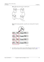
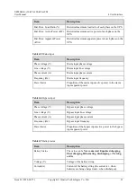
shows the cable connections for an NC EPO switch.
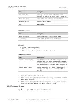
shows the cable connections for an NO EPO switch.
Figure 3-39
Cable connection for an NC EPO switch
Figure 3-40
Cable connection for an NO EPO switch
When the EPO switch is in the NC state, remove the jumper between EPO_NC and EPO_12V
before connection. When the EPO switch is turned off, EPO is triggered.
When the EPO switch is in the NO state, ensure that the jumper is connected between EPO_NC and
EPO_12V. When the EPO switch is turned on, EPO is triggered.
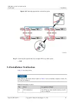
3.2.7 Connecting Communications Cables
Procedure
Step 1
Connect the external network management device to the RS485 port of the monitoring
interface card.
Step 2
Connect the network port on a PC to the FE port of the monitoring interface card.
----End


