background image

Alarm

ID

Alarm

Name

Seve

rity

Clearance

Condition

Trigger

Condition

Impact

on the

Syste

m

Suggestion

80

Parallel

CAN

signal

fault

Critic

al

You need

to

manually

rectify the

fault or

power off

and

restart the

device.

CAN

communication

signals are lost

for 6s in a

parallel system.

The

system

shuts

down

the

inverte

r and

transfe

rs to

bypass

mode.

If other

UPSs in

the

parallel

system

can

deliver

output

in

inverte

r

mode,

the

UPS

that

has

genera

ted the

alarm

deliver

s no

output.

● Possible cause: The circuit

is faulty.

Measure: Send the device to

the maintenance center.
● Possible cause: The

parallel cable is

disconnected.

Measure: Check the cable

connection.

UPS2000-G-3KRTLL

User Manual

4 Control Panel

Issue 01 (2020-10-26)

Copyright © Huawei Technologies Co., Ltd.

86

Summary of Contents for UPS2000-G-3KRTLL

Page 1: ...UPS2000 G 3KRTLL User Manual Issue 01 Date 2020 10 26 HUAWEI TECHNOLOGIES CO LTD ...

Page 2: ...cribed in this document may not be within the purchase scope or the usage scope Unless otherwise specified in the contract all statements information and recommendations in this document are provided AS IS without warranties guarantees or representations of any kind either express or implied The information in this document is subject to change without notice Every effort has been made in the prep...

Page 3: ...r additional measures to prevent radio frequency interferences Intended Audience This document is intended for Sales engineers Technical support engineers System engineers Hardware installation engineers Commissioning engineers Data configuration engineers Maintenance engineers Symbol Conventions The symbols that may be found in this document are defined as follows Symbol Description Indicates a h...

Page 4: ...ration or unanticipated results NOTICE is used to address practices not related to personal injury Supplements the important information in the main text NOTE is used to address information not related to personal injury equipment damage and environment deterioration Change History Changes between document issues are cumulative The latest document issue contains all updates made in previous issues...

Page 5: ... Ports 16 2 5 Battery Module 18 3 Installation 23 3 1 Installation Preparations 23 3 2 Installation Tools 24 3 3 Installing a UPS 25 3 4 Preparing Power Cables 27 3 5 Installing Cables for a Single UPS 28 3 6 Installing Cables for Parallel UPSs 30 3 7 Installing Communications Cables 33 3 8 Verifying the Installation 34 4 Control Panel 36 4 1 LCD Introduction 36 4 1 1 LCD 36 4 1 2 Buttons 39 4 1 3...

Page 6: ...sing Mains Power 97 5 3 1 2 Cold Starting the UPSs Using Batteries 99 5 3 2 Shutting Down a Parallel System 100 5 3 3 Performing EPO 101 6 UPS Maintenance 102 7 Technical Specifications 104 7 1 Physical Specifications 104 7 2 Environmental Specifications 104 7 3 Mains Input Electrical Specifications 105 7 4 Bypass Input Electrical Specifications 105 7 5 Output Electrical Specifications 106 7 6 Bat...

Page 7: ...d under the warranty Follow local laws and regulations when installing operating or maintaining the equipment The safety instructions in this document are only supplements to local laws and regulations Huawei will not be liable for any consequences of the following circumstances Operation beyond the conditions specified in this document Installation or use in environments which are not specified i...

Page 8: ...rocedures for installation operation and maintenance Before handling a conductor surface or terminal measure the contact point voltage and ensure that there is no risk of electric shock After installing the equipment remove idle packing materials such as cartons foam plastics and cable ties from the equipment area In the case of a fire immediately leave the building or the equipment area and turn ...

Page 9: ...a long period of time Before operations ensure that the equipment is firmly secured to the floor or other solid objects such as a wall or an installation rack Do not use water to clean electrical components inside or outside of a cabinet Do not change the structure or installation sequence of equipment without permission Do not touch a running fan with your fingers components screws tools or board...

Page 10: ...al hazards in equipment installation operation maintenance Trained personnel personnel who are technically trained have required experience are aware of possible hazards on themselves in certain operations and are able to take protective measures to minimize the hazards on themselves and other people Operators operation personnel who may come in contact with the equipment except trained personnel ...

Page 11: ... 30 mm exists between the cables and heat generating components or areas This prevents damage to the insulation layer of the cables Do not route cables behind the air intake and exhaust vents of the equipment Ensure that cables meet the VW 1 or ZB flame spread rating requirements or higher Bind cables of the same type together When routing cables of different types ensure that they are at least 30...

Page 12: ... requirements 1 4 Installation Environment Requirements To prevent fire due to high temperature ensure that the ventilation vents or heat dissipation system are not blocked when the equipment is running Install the equipment in an area far away from liquids Do not install it under areas prone to condensation such as under water pipes and air exhaust vents or areas prone to water leakage such as ai...

Page 13: ... not slide off Set a restricted area and eye catching signs for working at heights to warn away irrelevant personnel Carry the operation machinery and tools properly to prevent them from falling off and causing injuries Personnel involving working at heights are not allowed to throw objects from the height to the ground or vice versa Objects should be transported by tough slings hanging baskets hi...

Page 14: ...working at heights When a step ladder is used ensure that the pull ropes are secured and the ladder is held firm Before using a ladder check that it is intact and confirm its load bearing capacity Do not overload it Ensure that the ladder is securely positioned The recommended angle for a ladder against the floor is 75 degrees as shown in the following figure An angle rule can be used to measure t...

Page 15: ...mage components or cables inside Metal shavings from drilling may short circuit boards inside the equipment Obtain the consent from the customer and subcontractor before drilling Wear goggles and protective gloves when drilling holes When drilling holes protect the equipment from shavings After drilling clean up any shavings that have accumulated inside or outside the equipment Moving Heavy Object...

Page 16: ...ed for commercial and industrial purposes only It cannot be used as a power supply for life support devices For power supply systems that are critical to significant economic interests or public order such as the national computing center military command system emergency command center railway signal system and control center civil aviation and air traffic control center airport command center fi...

Page 17: ...is not applicable to pure capacitive loads pure inductive loads half wave rectification loads or regenerative loads Any operation on any electrical device in an environment that has inflammable air can cause extreme danger Strictly obey the operating environmental requirements specified in related user manuals when using or storing the device Do not use the UPS in the following places Environments...

Page 18: ...plode The site must be equipped with qualified fire extinguishing facilities such as firefighting sands and powder fire extinguishers NOTICE To ensure battery safety and battery management accuracy use batteries provided with the UPS by Huawei Huawei is not responsible for any battery faults caused by batteries not provided by Huawei Battery Installation Before installing batteries observe the fol...

Page 19: ...lithium battery loop disconnected during installation and maintenance Do not charge a battery when the ambient temperature is below the lower limit of the operating temperature charging is forbidden at 0 C Low temperature charging may cause crystallization which will result in a short circuit inside the battery Use batteries within the allowed temperature range otherwise the battery performance an...

Page 20: ...is abbreviated to a 3 kVA UPS in this document Figure 2 1 UPS model number Table 2 2 UPS model number details No Meaning Description 1 Product category UPS uninterruptible power system 2 Product family 2000 3 Product series G series name 4 Output capacity 3K 3 kVA UPS2000 G 3KRTLL User Manual 2 System Composition Issue 01 2020 10 26 Copyright Huawei Technologies Co Ltd 14 ...

Page 21: ...rnal large capacity batteries that provide long backup time 7 External battery type L LFP battery 2 2 Working Principle Figure 2 2 Conceptual diagram 2 3 Product Structure Figure 2 3 Front and rear views of a 3 kVA UPS UPS2000 G 3KRTLL User Manual 2 System Composition Issue 01 2020 10 26 Copyright Huawei Technologies Co Ltd 15 ...

Page 22: ...S232 port cannot be used at the same time a The USB port supports the serial port communication protocol The USB port can be used to export logs and send serial port commissioning commands b The RS232 port supports the serial port communication protocol The RS232 port can be used to export logs send serial port commissioning commands and upgrade the UPS main power program online 2 4 Communication ...

Page 23: ... the baud rate of 9600 bit s 4 A Data 5 B Data 6 NC Reserved pin 7 NC Reserved pin 8 GND Signal ground Table 2 5 Pin definitions for the BMS port Pin Signal Meaning Description 1 A Data Pins 1 and 4 are short circuited pins 2 and 5 are short circuited communicating with the lithium battery Supports the baud rate of 9600 bit s 2 B Data 3 NC Reserved pin 4 A Data UPS2000 G 3KRTLL User Manual 2 Syste...

Page 24: ...me Description 1 GND Protective ground M6 screw 2 DO1 DO2 ESM dry contact output Reserved 3 COM_ IN Communications port 1 The ports are used for information reporting and communication cascading 2 The ports use RJ45 terminals and provide the 1000 A surge protection capability 4 COM_ OUT Communications port 5 RUN Running indicator For details about indicator functions see the LED indicator descript...

Page 25: ...e terminal Positive and negative ports of the ESM They are secured by M6 screws Appropriate OT terminals should be used The required torque is 4 5 5 5 N m and the recommended cable size is 25 mm2 If the ESM is used at a temperature below 45 C the cable size can be smaller but should be at least 16 mm2 ESM negative terminal LED Indicators Figure 2 7 LED indicators UPS2000 G 3KRTLL User Manual 2 Sys...

Page 26: ... in sleep mode Blinking fast Communication is interrupted ALM Fault indicator Red Steady on There is a fault or major alarm Steady off There is no fault or major alarm CHG Charge indicator Green Steady on The ESM is being charged Steady off The ESM is open circuited or discharging DCHG Discharge indicator Green Steady on The ESM is being discharged Steady off The ESM is open circuited or being cha...

Page 27: ...ng slowly on for 1s and then off for 1s Blinking fast on for 0 125s and then off for 0 125s If the SOC indicators are off and other indicators are blinking the ESM enters the maintenance mode When the ESM is in sleep mode the fault indicator is off except for reverse connection protection Activation and Startup An ESM can be activated in the following two modes After being activated the ESM switch...

Page 28: ...the operation is ineffective 2 If you have powered off the ESM that is in charging discharging or disconnected mode by holding down the MANUAL ON OFF button you need to hold down this button again to reactivate the ESM UPS2000 G 3KRTLL User Manual 2 System Composition Issue 01 2020 10 26 Copyright Huawei Technologies Co Ltd 22 ...

Page 29: ...lammable and explosive substances Install the UPS in an environment free of dust volatile gas salt and corrosive materials Avoid direct sunlight Do not install the UPS in environments with conductive metal scraps in the air The optimal operating temperatures for batteries are 20 30 C Operating temperatures higher than 30 C shorten the battery lifespan and operating temperatures lower than 20 C red...

Page 30: ...ed during installation Table 3 1 Tools Appearance Specifications and Name Clamp meter Multimeter Labels Phillips screwdriver PH2 x 150 mm or PH3 x 250 mm Flat head screwdriver 2 mm x 80 mm Torque screwdriver Crimping tool Diagonal pliers UPS2000 G 3KRTLL User Manual 3 Installation Issue 01 2020 10 26 Copyright Huawei Technologies Co Ltd 24 ...

Page 31: ... the battery communications port and the cabinet for installing a communications cable Reserve a space of 44 mm between the battery edge and the rack edge for installing battery power cables In rack mounted installation scenarios the front panels of the UPS and lithium batteries are not on the same plane 1 Install the mounting ears on both sides of the UPS 2 Install the guide rails on the rack and...

Page 32: ... Rack mounted installation two UPSs and two lithium batteries Figure 3 3 UPS mounting ear dimensions unit mm UPS2000 G 3KRTLL User Manual 3 Installation Issue 01 2020 10 26 Copyright Huawei Technologies Co Ltd 26 ...

Page 33: ... terminals The UPS battery input terminal has a voltage of 56 V 10 seconds before batteries are connected Table 3 2 Recommended power cable specifications Model Wiring Termina l Numb er of Phase s Rated Voltage External Circuit Breaker Cable Cross section al Area Terminal Type Torque for Tighteni ng Bolts 3kVA AC input and output 1 220 V AC 230 V AC 240 V AC 16 A type D 2 5mm2 OT 6 mm2 M5 terminal...

Page 34: ... two lithium batteries connected in parallel as an example The maximum discharge current of a 50 Ah lithium battery is 4 kW The maximum discharge current of a 100 Ah or 150 Ah lithium battery is 4 3 kW When lithium batteries are connected it is recommended that a DC circuit breaker 63 A 80 V DC circuit breaker for the 3 kVA UPS be installed between the lithium batteries and the UPS Before connecti...

Page 35: ...ttery cables rack mounted front view 1 UPS rear view 2 Busbar Figure 3 6 Installing battery cables rack mounted rear view UPS2000 G 3KRTLL User Manual 3 Installation Issue 01 2020 10 26 Copyright Huawei Technologies Co Ltd 29 ...

Page 36: ...arallel running Installing Power Cables 1 Switch off the upstream AC circuit breaker for the UPS 2 Remove the AC input AC output and battery input terminal cover from each UPS 3 Install AC output power cables AC input power cables and then battery input cables in sequence Figure 3 8 AC input AC output and battery input wiring diagram sharing battery strings UPS2000 G 3KRTLL User Manual 3 Installat...

Page 37: ...in parallel connect signal cables to the BMS ports on the UPS Install a build out resistor at the COM OUT port on the last lithium battery UPS sharing battery strings Figure 3 10 Installing battery cables rack mounted front view 1 UPS rear view 2 Busbar UPS2000 G 3KRTLL User Manual 3 Installation Issue 01 2020 10 26 Copyright Huawei Technologies Co Ltd 31 ...

Page 38: ...s rack mounted rear view UPS not sharing battery strings Figure 3 12 Installing battery cables rack mounted front view 1 UPS rear view UPS2000 G 3KRTLL User Manual 3 Installation Issue 01 2020 10 26 Copyright Huawei Technologies Co Ltd 32 ...

Page 39: ... parallel communications cables and parallel current equalization cables 1 Parallel current equalization cables 2 Parallel communications cables 3 7 Installing Communications Cables UPS2000 G 3KRTLL User Manual 3 Installation Issue 01 2020 10 26 Copyright Huawei Technologies Co Ltd 33 ...

Page 40: ... Bolts are tightened to specified torque using a torque wrench 3 Cable connection to USB network and other ports Signal cables to USB network and other ports are connected securely and correctly 4 Cable labels Labels are neatly attached to both ends of each cable and the information on the labels is concise and legible 5 Ground cable connection The UPS ground cable is securely connected to the equ...

Page 41: ...esult 7 Operating environment The inside and outside of the cabinet are free from conductive dust or other sundries UPS2000 G 3KRTLL User Manual 3 Installation Issue 01 2020 10 26 Copyright Huawei Technologies Co Ltd 35 ...

Page 42: ...ted on the front panel of the chassis The control panel allows you to control and operate the UPS view the running status set parameters and view alarms 4 1 1 LCD UPS2000 G 3KRTLL User Manual 4 Control Panel Issue 01 2020 10 26 Copyright Huawei Technologies Co Ltd 36 ...

Page 43: ... output current Displays the current load percentage by level 0 24 Indicator 1 is steady on 25 49 Indicators 1 and 2 are steady on 50 74 Indicators 1 2 and 3 are steady on 75 100 Indicators 1 2 3 and 4 are steady on Indicates that the mains is connected Indicates that batteries are discharging Indicates that batteries are being charged Indicates that the UPS is in bypass mode Indicates that the UP...

Page 44: ... batteries are connected in parallel this area displays the lowest SOC among the connected batteries Indicates the remaining battery backup time H hour M minute S second Indicates the UPS parallel connection status If the icon is not displayed the UPS is in single node mode Indicates that the UPS is muted UPS2000 G 3KRTLL User Manual 4 Control Panel Issue 01 2020 10 26 Copyright Huawei Technologie...

Page 45: ... up Start the UPS inverter Press and hold ON MUTE for more than 5s The UPS inverter starts Stop the buzzer If there is an alarm press and hold ON MUTE for more than 2s in non setting mode to mute the current alarm When the UPS generates a new alarm the mute function becomes ineffective If you need to mute the alarm perform the mute operation again Go to the previous item When the LCD is on press O...

Page 46: ...t the same time for 3s on the password login screen 5 ON MUTE SELECT Exit Press ON MUTE and SELECT at the same time to exit the current screen go to the upper level menu from the setting screen or go to the default screen from the selection screen 4 1 3 LCD Screen Information You can press SELECT to switch the information displayed on the LCD in sequence The information is displayed in the followi...

Page 47: ...age default screen Input frequency Output voltage Battery voltage Output frequency Battery voltage Load percentage 3 as shown in the figure Charge current AC discharge current UPS2000 G 3KRTLL User Manual 4 Control Panel Issue 01 2020 10 26 Copyright Huawei Technologies Co Ltd 41 ...

Page 48: ...ftware version visit https support huawei com carrier docview nid DOC1100723472 to download the upgrade guide 4 2 LCD Character Display Table 4 4 LCD character display description Abbreviation Display Meaning ADS Communication address BP Battery not connected UPS2000 G 3KRTLL User Manual 4 Control Panel Issue 01 2020 10 26 Copyright Huawei Technologies Co Ltd 42 ...

Page 49: ...ENA Enabled Err Error ESC Exit the setting mode ESP Automatically return to the default screen FBT Shallow discharge test FLV Float charge voltage FrE Frequency FrS Manual alarm clearance HS Host NE New not connected to the parallel system NUM Set the number of parallel UPSs PAS Password input rST Restore factory settings UPS2000 G 3KRTLL User Manual 4 Control Panel Issue 01 2020 10 26 Copyright H...

Page 50: ...MUTE SELECT and OFF ENTER at the same time for 3s on the password login screen to reset the password If you enter incorrect passwords for multiple times the password input screen will be locked and you cannot continue to enter the password The following table lists the detailed data Table 4 5 Mapping between incorrect password attempts and lockout duration Incorrect Password Attempts Lockout Durat...

Page 51: ... Display 10 Attempts 60 minutes 59 minutes and 59 seconds are displayed as 59 and seconds are not displayed Figure 4 2 Password input screen UPS2000 G 3KRTLL User Manual 4 Control Panel Issue 01 2020 10 26 Copyright Huawei Technologies Co Ltd 45 ...

Page 52: ... Default value 10 A Value range 10 30 A The value increases by 10 A each time you press SELECT Output voltage You need to shut down the inverter before changing the output voltage 220 indicates that the output voltage is 220 V AC 230 indicates that the output voltage is 230 V AC default value 240 indicates that the output voltage is 240 V AC Set the number of parallel UPSs Default value 1 Value ra...

Page 53: ... sharing enabled When setting the battery capacity set the total battery string capacity for each UPS Battery string sharing disabled When setting the battery capacity set the capacity of the battery string connected to each UPS Output frequency You need to shut down the inverter before changing the output frequency 50 Hz default 60 Hz UPS2000 G 3KRTLL User Manual 4 Control Panel Issue 01 2020 10 ...

Page 54: ... default ENA Enable shallow discharge test The shallow discharge test time is controlled by the battery discharge time and discharge percentage Discharge percentage 20 default Value range 10 50 The value increases by 1 each time you press SELECT Buzzer off setting Enable or disable the buzzer off function ENA Enable the buzzer off function DIS Disable the buzzer off function disabled by default UP...

Page 55: ...ntly turned on by the user Equalized charge voltage Default value 54 0 V When the lithium battery does not communicate the value range is 53 5 57 0 V The value increases by 0 1 V each time you press SELECT When the lithium battery is communicating the UPS automatically adapts to the equalized charging voltage based on the connected lithium battery model The value is fixed and cannot be changed UPS...

Page 56: ...e is fixed and cannot be changed Battery EOD point Default value 44 0 V Value range 44 0 46 0 V The value increases by 0 1 V each time you press SELECT The battery EOD threshold is fixed at the current value regardless of the load percentage Set the communications address The default communications address is 001 which is used for the RS485 communications ports connect to northbound devices Set di...

Page 57: ...d a password is required for accessing the settings screen DIS Disable LCD password control After LCD password control is disabled no password is required for accessing the setting screen However other users may have the permission to access the parameter setting screen to modify parameters Password setting Initial password 000001 You are advised to change the initial password after installation O...

Page 58: ... Deep discharge test DIS Disable battery deep discharge test default ENA Enable battery deep discharge test This function can be enabled only when the battery SOC is 100 Battery string sharing ENA Enable battery string sharing default DIS Disable battery string sharing Exit the setting mode ESC Exit the setting mode UPS2000 G 3KRTLL User Manual 4 Control Panel Issue 01 2020 10 26 Copyright Huawei ...

Page 59: ...he UPS enters the fault mode Table 4 7 Operating mode description Operating Mode Description Display Standby mode The UPS does not supply power but it can still charge batteries Charging batteries with mains power Not charging batteries Bypass mode The UPS supplies mains power The mains power can be used to charge batteries Charging batteries with mains power UPS2000 G 3KRTLL User Manual 4 Control...

Page 60: ...n be used to charge batteries Charging batteries with mains power Not charging batteries Fault mode The UPS supplies mains power through the bypass Not charging batteries supplying mains power through the bypass UPS2000 G 3KRTLL User Manual 4 Control Panel Issue 01 2020 10 26 Copyright Huawei Technologies Co Ltd 54 ...

Page 61: ... charges batteries if they are connected Not charging batteries Charging batteries with mains power Battery mode The UPS supplies battery power Supplying only battery power 4 5 Alarm Types 4 5 1 Critical Alarms UPS2000 G 3KRTLL User Manual 4 Control Panel Issue 01 2020 10 26 Copyright Huawei Technologies Co Ltd 55 ...

Page 62: ...eaning 02 Overtemperature 03 Battery overvoltage 05 Output short circuit detected by the internal converter 06 Output overvoltage 07 Download timeout 08 Bus overvoltage 09 Bus soft start failure 50 PFC overcurrent 51 Output overcurrent 52 Bus undervoltage 53 UPS soft start failure 55 DC overvoltage in AC output 57 Current sensor fault 58 Output undervoltage 60 Load backfeed 71 Inconsistent paralle...

Page 63: ...r sounds twice every 3s If there is an alarm press ON MUTE for more than 2s in non setting mode to mute the current alarm When the UPS generates a new alarm the mute function becomes ineffective If you need to mute the alarm perform the mute operation again Table 4 9 Minor alarms Code Display Meaning 01 Fan locked during UPS startup 04 Battery voltage below the EOD threshold 12 Manual bypass activ...

Page 64: ...ass mode 32 UPS locked in bypass mode due to three transfers to bypass mode 33 Overtemperature 34 Inconsistent number of parallel UPSs 35 Long time inverter current imbalance 36 Overload 37 The inverter switch is off in ECO mode 38 The number of started inverters is insufficient to carry the load 39 Output in battery mode 40 Inconsistent battery capacity 41 Lithium battery high voltage protection ...

Page 65: ...e 46 Lithium battery reverse connection protection 48 ECO missing 49 Inconsistency between lithium battery capacity and battery capacity setting 59 Charger circuit overcurrent BP Battery not connected UPS2000 G 3KRTLL User Manual 4 Control Panel Issue 01 2020 10 26 Copyright Huawei Technologies Co Ltd 59 ...

Page 66: ...n blockage signal is at low level for 15s within 30s The current workin g status is not affecte d If overte mperat ure protect ion is trigger ed the system may transfe r to bypass mode Possible cause The fan is blocked Measure Check the fan and remove sundries Possible cause The fan is faulty Measure Replace the fan UPS2000 G 3KRTLL User Manual 4 Control Panel Issue 01 2020 10 26 Copyright Huawei ...

Page 67: ...ree times After that you need to manually clear the alarm Fan blocked The highest temperature of internal components exceeds 90 C for 100 ms Fan not blocked The highest temperature of internal components exceeds 80 C for 100 ms The system shuts down the inverte r and transfe rs to bypass mode Possible cause The temperature is too high Measure Decrease the ambient temperature or load Possible cause...

Page 68: ...ental factors Measure Send the device to the maintenance center 04 Low battery voltage Mino r The battery voltage is higher than the EOD threshold and the mains is connected properly The battery voltage is lower than the EOD threshold The system cannot supply power in battery mode If this alarm is genera ted in battery mode the power output will be discon nected Possible cause The battery is fault...

Page 69: ... You need to manually rectify the fault or power off and restart the device The output voltage exceeds the rated voltage by 20 V for 3s The system shuts down the inverte r and transfe rs to bypass mode Possible cause Load energy backfeed occurs Measure Locate the load and remove it Possible cause The circuit is faulty Measure Send the device to the maintenance center 07 Downl oad timeou t Critic a...

Page 70: ...llel Measure Check that the parallel cable and current equalization cable are properly connected Possible cause The circuit is faulty Measure Send the device to the maintenance center 09 Bus short circuit Critic al You need to manually rectify the fault or power off and restart the device The bus soft start time exceeds 15s The system cannot start inverte r output and transfe rs to bypass mode Pos...

Page 71: ...s unstable 17 Bypass abnor mal Mino r The bypass voltage or frequency recovers to the normal range The bypass voltage or frequency is out of the normal range The syst em can not tran sfer to byp ass mod e whe n a criti cal alar m is gen erat ed In byp ass mod e the pow er out put is disc onn ecte d Check that the bypass connection is normal Check that the bypass voltage and frequency are within th...

Page 72: ...ter workin g for a period of time Possible cause The battery charge level is low Measure Charge the battery 19 Abnor mal mains voltage Mino r The mains voltage input recovers The mains is disconnected or fails The mains input voltage harmonic exceeds 10 square wave input is not supported The mains frequency change rate exceeds the phase lock rate defined in the specifications 2 Hz s for a single U...

Page 73: ...battery cannot be recovered due to protection against abnormality contact local Huawei engineers to rectify the fault 21 Lithium battery low temper ature protecti on Mino r The cell temperatu re rises above the protection threshold Charge low temperature protection The minimum cell temperature is less than 0 C Discharge low temperature protection The minimum cell temperature is less than 20 C The ...

Page 74: ...oo fast or the internal resistance is too large Measure If the lithium battery cannot be recovered due to protection against abnormality contact local Huawei engineers to rectify the fault 24 Lithium battery overcur rent protecti on Mino r The battery discharge current drops below the protection threshold Discharge current 0 93 times of the current limit and Vbus 40 V for 15s Discharge current 0 9...

Page 75: ...h off the battery shallow or deep discharge test mode 28 The battery dischar ge time reaches the maxim um Mino r Set item 05 battery discharge time to 0 or restart the inverter The battery discharge time reaches the preset value The system cannot supply power in battery mode If this alarm is genera ted in battery mode the power output will be discon nected Check whether the mains input is normal U...

Page 76: ...ed if the bypass input is abnor mal Check whether the UPS transfers to bypass mode due to overload Check whether the inverter switch is turned on 32 UPS locked in bypass state Mino r The inverter switch is turned on again The UPS transfers to bypass mode more than three times within 30 minutes due to overload The system cannot autom atically switch back to inverte r mode Possible cause The UPS is ...

Page 77: ...an not blocked The highest temperature of internal components exceeds 87 C for 100 ms If the interna l temper ature of the system is close to the overte mperat ure protect ion thresho ld a critical overte mperat ure alarm may be trigger ed and the system will transfe r to bypass mode Possible cause The temperature is too high Measure Decrease the ambient temperature or load Possible cause The temp...

Page 78: ...uggestion Set the number of parallel UPSs to the actual value 35 Long time current imbala nce Mino r The difference between the UPS load percentag e and the parallel system load percentag e is within 10 for 10s The difference between the UPS load percentage and the parallel system load percentage is greater than 20 for 10s The current workin g status is not affecte d The system may transfe r to by...

Page 79: ...ECO mode When the mains input exceed s the ECO range the power supply is discon nected The inverter output switch is turned on 38 The numbe r of started inverter s is insuffici ent to carry the load Mino r The inverter switches of other UPSs in the parallel system are turned on In parallel mode the number of started inverters is insufficient to support the actual load The system keeps workin g in ...

Page 80: ...tion of minor alarm 19 The current workin g status is not affecte d When the battery backup time or dischar ge time reaches the preset value the system will discon nect the power output Check whether the mains input is normal Possible cause The circuit is faulty Send the device to the maintenance center UPS2000 G 3KRTLL User Manual 4 Control Panel Issue 01 2020 10 26 Copyright Huawei Technologies ...

Page 81: ...he maximum discharge power of lithium batteries is less than the actual load power of the UPS After the UPS transfe rs to battery mode the lithium battery overcur rent protect ion may be trigger ed which causes the system to power off Reduce the load or add lithium batteries in a timely manner UPS2000 G 3KRTLL User Manual 4 Control Panel Issue 01 2020 10 26 Copyright Huawei Technologies Co Ltd 75 ...

Page 82: ...large Measure If the lithium battery cannot be recovered due to protection against abnormality contact local Huawei engineers to rectify the fault 43 Lithium battery fault Mino r The alarm is not cleared After batteries are reset check the status again The cell voltage sampling circuit is faulty The cell temperature sampling circuit is faulty The cell voltage is too high or too low The cell temper...

Page 83: ... d or dischar ged Possible cause The UPS is overloaded the host charger is abnormal or battery cables are incorrectly connected Measure Check the cable connection check the host status or reduce the load 45 Charge r shutdo wn due to lithium battery commu nicatio n failure Mino r Lithium battery communic ation recovers Lithium battery communication is unavailable for 40s The SOC data and backup tim...

Page 84: ... or has no output Measure Check the battery switch status and battery cable connection 48 ECO missing Mino r The input voltage and frequency restore to the normal range in ECO mode The input voltage or frequency exceeds the normal operating range in ECO mode The UPS cannot transfe r to bypass mode If the UPS is workin g in bypass mode it transfe rs to anothe r workin g mode Possible cause The ECO ...

Page 85: ...may be shorten ed Check that the UPS battery capacity setting matches the lithium battery capacity Check whether abnormal lithium battery communication causes an error in capacity reading 50 PFC overcur rent Critic al The alarm is automatic ally cleared Inverter not started The PFC current exceeds 65 A for 10 ms Inverter started The PFC current exceeds 65 A for 260 μs The system shuts down the inv...

Page 86: ... less than 7 times the battery voltage Normal mode The bus voltage is over 80 V less than the peak mains voltage The system shuts down the inverte r and transfe rs to bypass mode Possible cause The transient load power is too high Measure Locate the load and remove it Possible cause The circuit is faulty Measure Send the device to the maintenance center 53 Timeou t in approa ching rated output vol...

Page 87: ...manually rectify the fault or power off and restart the device In power on mode the current sampling deviation exceeds 10 of the total sampling range The system cannot start the inverte r and directly deliver s output in bypass mode Possible cause The circuit is faulty Measure Send the device to the maintenance center 58 Low output voltage Critic al You need to manually rectify the fault or power ...

Page 88: ...t is damaged Measure Replace the charger circuit 60 Load backfee d detecte d Critic al You need to manually rectify the fault or power off and restart the device When UPSs are connected in parallel the output backfeed power exceeds 1200 W for 100 ms The system shuts down the inverte r and transfe rs to bypass mode If other UPSs in the parallel system can deliver output in inverte r mode the UPS th...

Page 89: ...llel UPS protocols are inconsistent If the version s are inconsi stent the non master UPS exits the parallel system Otherw ise the UPS transfe rs to bypass mode becaus e the numbe r of parallel UPSs is inconsi stent Possible cause The UPS software versions are inconsistent Measure Upgrade the software to the same version UPS2000 G 3KRTLL User Manual 4 Control Panel Issue 01 2020 10 26 Copyright Hu...

Page 90: ...Equalized current sampling is abnormal The system shuts down the inverte r and transfe rs to bypass mode If other UPSs in the parallel system can deliver output in inverte r mode the UPS that has genera ted the alarm deliver s no output Possible cause The circuit is faulty Measure Send the device to the maintenance center UPS2000 G 3KRTLL User Manual 4 Control Panel Issue 01 2020 10 26 Copyright H...

Page 91: ...ltage settings of parallel UPSs are inconsistent If the output voltage setting s are inconsi stent the non master UPS exits the parallel system Otherw ise the UPS transfe rs to bypass mode becaus e the numbe r of parallel UPSs is inconsi stent Possible cause The output settings are inconsistent Measure Set the output voltages to the same value UPS2000 G 3KRTLL User Manual 4 Control Panel Issue 01 ...

Page 92: ...em The system shuts down the inverte r and transfe rs to bypass mode If other UPSs in the parallel system can deliver output in inverte r mode the UPS that has genera ted the alarm deliver s no output Possible cause The circuit is faulty Measure Send the device to the maintenance center Possible cause The parallel cable is disconnected Measure Check the cable connection UPS2000 G 3KRTLL User Manua...

Page 93: ...l is lost for more than 60 ms in a parallel system The system shuts down the inverte r and transfe rs to bypass mode If other UPSs in the parallel system can deliver output in inverte r mode the UPS that has genera ted the alarm deliver s no output Possible cause The circuit is faulty Measure Send the device to the maintenance center UPS2000 G 3KRTLL User Manual 4 Control Panel Issue 01 2020 10 26...

Page 94: ...ation zero crossing signal is lost for more than 200 ms The system shuts down the inverte r and transfe rs to bypass mode If other UPSs in the parallel system can deliver output in inverte r mode the UPS that has genera ted the alarm deliver s no output Possible cause The circuit is faulty Measure Send the device to the maintenance center UPS2000 G 3KRTLL User Manual 4 Control Panel Issue 01 2020 ...

Page 95: ...iation between UPSs in a parallel system is greater than 4 V for 120 ms The system shuts down the inverte r and transfe rs to bypass mode If other UPSs in the parallel system can deliver output in inverte r mode the UPS that has genera ted the alarm deliver s no output Possible cause Batteries are not shared Measure Ensure that all UPSs share one battery string UPS2000 G 3KRTLL User Manual 4 Contr...

Page 96: ... mode If other UPSs in the parallel system can deliver output in inverte r mode the UPS that has genera ted the alarm deliver s no output Possible cause The UPSs do not share one mains supply Measure Ensure that all UPSs share one mains supply 87 EPO trigger ed Critic al The EPO open circuit status needs to be restored and the alarm needs to be manually cleared The EPO port is short circuited The ...

Page 97: ...n ways that facilitate modification capacity expansion and maintenance The UPS is properly grounded The voltage between the neutral wire and the ground cable is less than 5 V AC 5 2 Single UPS Operations 5 2 1 Starting a UPS NOTICE If no button is pressed within 20s in UPS setting mode the LCD home screen is displayed If no batteries are connected to the UPS of the long backup time model the buzze...

Page 98: ...ternal AC input circuit breaker Km for the UPS The UPS will enter the bypass mode Press and hold SELECT for 1s on a non setting screen to access the login screen for parameter settings The initial password is 000001 Enter the correct password to access the UPS setting mode UPS2000 G 3KRTLL User Manual 5 Operations Issue 01 2020 10 26 Copyright Huawei Technologies Co Ltd 92 ...

Page 99: ...on You need to shut down the inverter before changing the output voltage 220 indicates that the output voltage is 220 V AC 230 indicates that the output voltage is 230 V AC default value 240 indicates that the output voltage is 240 V AC UPS2000 G 3KRTLL User Manual 5 Operations Issue 01 2020 10 26 Copyright Huawei Technologies Co Ltd 93 ...

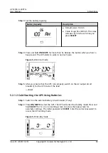
Page 100: ...tch on the AC output circuit breaker Q for the UPS to start the load End 5 2 1 2 Cold Starting the UPS Using Batteries Step 1 Switch on the external battery circuit breaker if any Step 2 Press ON MUTE to start the UPS The UPS will enter the standby mode Press and hold SELECT for 1s on a non setting screen to access the login screen for parameter settings The initial password is 000001 Enter the co...

Page 101: ...e battery capacity Battery Capacity Description Default value 100 Ah Value range 50 2400 Ah The value increases by 50 Ah each time you press SELECT Step 5 Press and hold ON MUTE for more than 5s Release the button when you hear a beep sound The UPS starts to work in battery mode Figure 5 6 Battery mode Step 6 After you ensure that the UPS runs properly switch on the AC output circuit breaker Q for...

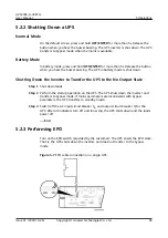
Page 102: ...Perform the startup operation on the UPS The UPS shuts down the inverter and transfers to bypass mode If mains parameters are inconsistent with bypass parameters the UPS transfers to standby mode Step 3 Switch off the AC input circuit breaker Km and output circuit breaker Q for the UPS After all indicators turn off and fans stop the UPS shuts down and the loads power off End 5 2 3 Performing EPO T...

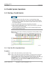
Page 103: ... power and then loads with lower power Figure 5 8 AC input output and battery wiring diagram sharing battery strings in this example 5 3 1 1 Start the UPSs Using Mains Power Procedure Step 1 Switch on the external battery circuit breaker if any Step 2 Switch on the general AC input circuit breaker Km to start the UPS The UPS will enter the bypass mode Switch on the AC output circuit breaker Q1 The...

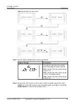
Page 104: ... 220 V AC 230 indicates that the output voltage is 230 V AC default value 240 indicates that the output voltage is 240 V AC Step 4 Operate the UPSs one by one to set the number of parallel output UPSs Press SELECT go to the setting screen and set parallel system parameters Press ON MUTE SELECT to return to the standby screen UPS2000 G 3KRTLL User Manual 5 Operations Issue 01 2020 10 26 Copyright H...

Page 105: ... setting screen to access the login screen for parameter settings The initial password is 000001 Enter the correct password to access the UPS setting mode Step 3 Set the output voltage based on site requirements Output Voltage Description You need to shut down the inverter before changing the output voltage 220 indicates that the output voltage is 220 V AC 230 indicates that the output voltage is ...

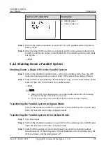
Page 106: ...the parallel system End NOTE When one UPS in the parallel system is shut down while another UPS is still working the UPS that has been shut down has no output To shut down a UPS without removing it from the system perform only step 1 Transferring the Parallel System to Bypass Mode Perform the shutdown operation on each UPS in the parallel system All UPSs shut down the inverters and transfer to byp...

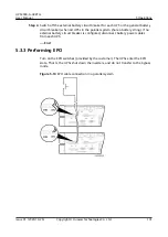
Page 107: ...ker is configured disconnect battery power cables from each UPS End 5 3 3 Performing EPO Turn on the EPO switches provided by the customer The UPSs enter the EPO state That is the UPSs shut down the inverters and do not transfer to the bypass mode Figure 5 10 EPO cable connection in a parallel system UPS2000 G 3KRTLL User Manual 5 Operations Issue 01 2020 10 26 Copyright Huawei Technologies Co Ltd...

Page 108: ...aintain UPSs regularly based on the following requirements Otherwise the UPSs may fail to operate properly and the lifespan may be shortened Table 6 1 UPS routine maintenance Item Expected Result Troubleshooting Maintenance Interval Operating environment Ambient temperature 0 40 C Humidity 0 95 RH non condensing If the humidity and temperature are abnormal check the air conditioner status If the i...

Page 109: ...the dust especially from the front panel Quarterly Parameter settings The settings of the output voltage level frequency and battery capacity meet requirements Reset the parameters Quarterly Power cables and terminals between the UPS and external power distribution equipment The insulation layers of cables are intact and terminals are free from noticeable sparks Replace the cables Secure the outpu...

Page 110: ...ecifications Table 7 2 Environmental specifications Item Specifications Operating temperature range 0 40 C not derated Humidity 0 95 RH non condensing Altitude 0 1000 m When the altitude is greater than 1000 m but less than 4000 m the power should be derated For details see IEC 62040 3 Storage and transportation temperatures 40 C to 70 C UPS2000 G 3KRTLL User Manual 7 Technical Specifications Issu...

Page 111: ...range 50 Hz 60 Hz 4 Hz Input power factor 0 98 100 load 0 94 50 load 0 86 30 load THDi 6 100 load 9 50 load 14 30 load Voltage detection precision 2 Generator input capacity 1 5 times the UPS capacity Inrush current five times the rated current Static withstand voltage 320 V AC input no damage to the UPS at least 2 hours 7 4 Bypass Input Electrical Specifications Table 7 4 Bypass input electrical ...

Page 112: ...ctrical Specifications Table 7 5 Output electrical specifications Item Specifications Rated capacity 3 kVA 2 7 kW Output power factor 0 9 Rated output voltage 220 V AC 230 V AC 240 V AC Output voltage precision 1 Output frequency When the mains is normal the UPS automatically tracks the mains frequency When the mains is abnormal the output frequency is 50 Hz tolerance 0 5 System efficiency Maximum...

Page 113: ...nverter mode to bypass mode Uninterruptible transfer 0 ms Interruptible transfer 10 ms Average frequency tracking rate Single UPS 2 Hz s Parallel system 1 Hz s Output dynamic response 5 0 100 100 0 load change Output regulated voltage precision 1 Load detection precision 5 7 6 Battery Electrical Specifications Table 7 6 Battery electrical specifications Item Specifications Battery type Lithium bat...

Page 114: ...ery voltage 48 V DC 50 Ah 100 Ah 51 2 V DC 150 Ah Battery quantity Single UPS Parallel system A maximum of eight batteries of the same model can be connected in parallel Charge current limit 10 30 A Equalized charge voltage 50 Ah 53 5 V DC 100 Ah 150 Ah 54 V DC Float charge voltage 50 Ah 51 V DC 100 Ah 150 Ah The battery float charge voltage is adjusted by the DC DC inside the BMS The UPS does not...

Page 115: ...fety and EMC Item Standards Compliance Conducted emission CE IEC 62040 2 C2 Radiated emission RE IEC 62040 2 C2 Low frequency signal immunity IEC 61000 2 2 ESD immunity IEC 61000 4 2 Conducted susceptibility CS IEC 61000 4 6 Radiated susceptibility RS IEC 61000 4 3 Electrical fast transient burst IEC 61000 4 4 Surge IEC 61000 4 5 Power frequency magnetic field IEC 61000 4 8 UPS2000 G 3KRTLL User M...

Page 116: ... 61000 3 12 Voltage dip IEC 61000 3 11 Impact current surge protection IEC EN 60240 2 IEC EN 61000 4 5 YD T 1095 2000 YD T 944 2007 UPS2000 G 3KRTLL User Manual 7 Technical Specifications Issue 01 2020 10 26 Copyright Huawei Technologies Co Ltd 110 ...

Page 117: ...PO emergency power off ECO economy control operation EOD end of discharge ESM energy storage module ESN equipment serial number H HTTPS Hypertext Transfer Protocol Secure L LCD liquid crystal display LSI large scale integrated M MIB management information base UPS2000 G 3KRTLL User Manual A Acronyms and Abbreviations Issue 01 2020 10 26 Copyright Huawei Technologies Co Ltd 111 ...

Page 118: ...rd 485 S SELV safety extra low voltage SSH Secure Shell T THDv total harmonic distortion of output voltage TNV telecommunication network voltage U UPS uninterruptible power system USB Universal Serial Bus V VRLA valve regulated lead acid UPS2000 G 3KRTLL User Manual A Acronyms and Abbreviations Issue 01 2020 10 26 Copyright Huawei Technologies Co Ltd 112 ...

Reviews: