TP48200A-DX08A1 and TP48200A-DX08A2 Telecom
Power
User Manual
4 Maintenance
Issue 06 (2019-11-15)
Copyright © Huawei Technologies Co., Ltd.
48
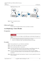
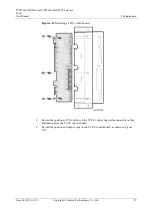
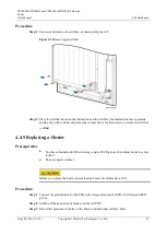
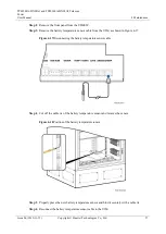
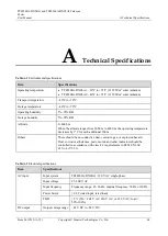
Figure 4-6
Removing the –48 V power cable
Step 6
Record the positions where the PCB connects to all the cables, and then disconnect the cables.
Step 7
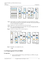
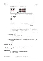
Remove the PCB as shown in Figure 4-7.
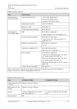
Figure 4-7
Removing the PCB of UIM02C
Step 8
Take out the new PCB and install it.
Step 9
Connect all cables back to the new PCB based on the record made previously.
Step 10
Connect the –48 V power cable to the user interface module.
Step 11
Push in the UIM02C and tighten the screws.
Step 12
Reconnect signal cables to the UIM02C panel based on the records made previously.
Step 13
Reinstall the front panel on the UIM02C.
Step 14
Disconnect the ground cable from the ESD wrist strap, and remove the ESD wrist strap or
ESD gloves.
----End


