


TP48200A-HX09A2 & TBC300A-TCA2
Installation Guide
6 Installing Components
Issue 01 (2013-10-25)
Huawei Proprietary and Confidential
Copyright © Huawei Technologies Co., Ltd.
50
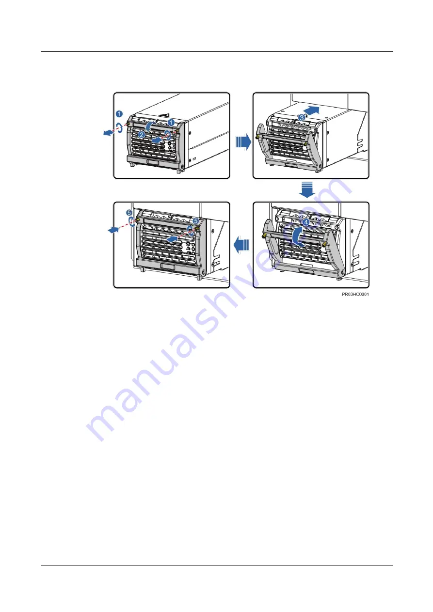
Figure 6-1
Installing a rectifier
----End
6.2 (Optional) Installing a Lamp
Procedure
Step 1
Hang a lamp on the right of the rack inside the power cabinet.
Step 2
Remove the panel from the PDU in the power system.
Step 3
Connect the negative lamp cable to the load circuit breaker F5 of the PDU.
Step 4
Connect the positive lamp cable to the RTN+ busbar.


