26
2
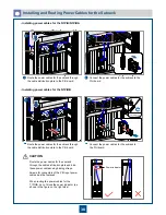
Installing and Routing Power Cables and PGND Cables
Installing and Routing Power Cables
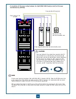
– DC Power Distribution Box
a
If the measured resistance between NEG(-) and RTN(+), and between NEG(-) and PGND bolt is less than
20 ohms, a short circuit occurs between the working power module and the working ground. In this case,
rectify the fault immediately, and then perform Step 4 again.
Ensure that the switches of the external power supply facilities are in the "OFF" position.
If a power monitoring device is configured for the power supply facilities, disconnect the power supply
facilities from the power monitoring device before measuring the resistance between the power terminals.
Otherwise, the measured resistance may be incorrect.
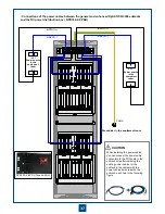
Multimeter
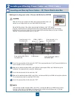
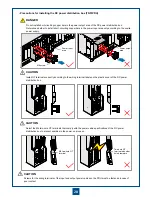
Turn all the power switches for the subrack to "OFF". These power switches are in the DC power distribution box,
which is located on the top of the cabinet.
Measure the resistance between NEG(-) and PGND bolt, and between RTN(+) and PGND bolt using the
multimeter. The measured value needs to be infinitely great.
Turn all the power switches for the subrack to "ON".
Measure the resistance between NEG(-) and RTN(+), and between NEG(-) and PGND bolt using the multimeter.
The measured value needs to more than 20,000 ohms.
Turn all the power switches for the subrack to "OFF".
•
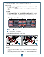
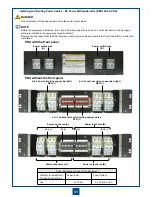
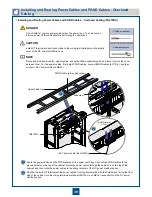
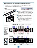
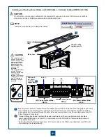
Installing and routing power cables
– DC power distribution box (N1PDU)
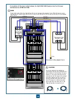
Power terminals 1-4 for
the subrack (left)
Power switches SW1-SW4 for
the subrack (left)
PGND terminal
Power switches SW1-SW4 for
the subrack (right)
Power terminals 1-4 for
the subrack (right)
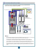
RTN1(+)
NEG2(-)
RTN2(+) NEG1(-)
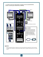
When two 32 A power inputs are available in the telecommunications room, one
cabinet can be configured with only one OptiX OSN 3500 III subrack.
NOTE
CAUTION


