57
2
1
1
Assembling OT Terminals and Power Cables
Assembling Cable Connectors
Heat gun
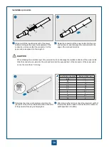
Components of an OT terminal and a power cable
Strip a part of the insulation layer C of the power
cable according to the cross-sectional area of the
conductor, and ensure that the conductor D of the
power cable is exposed for the length L1.
Route the power cable into the heat shrink tubing A.
Route the exposed conductor of the power cable into
the OT terminal B, and then maintain the OT terminal
close to the insulation layer C of the power cable.
Installation procedure
C
D
A
B
Heat shrink tubing
Bare crimp terminal
Insulation layer of a power cable
Conductor of a power cable
A
B
C
D
B
C
D
L
L1
When stripping the insulation layer of a power cable, do not damage the metallic conductor of the power cable.
If the bare crimp terminal is not provided by Huawei, change the value of L1 according to the actual value L of
the bare crimp terminal. L1 = L + (1-2) mm.
After the conductor is routed into the OT terminal, the exposed part L2 of the conductor of the power cable
cannot be more than 2 mm.
A
C
B
L2
Utility knife
Summary of Contents for OptiX OSN 2500
Page 1: ...HUAWEI TECHNOLOGIES CO LTD OptiX OSN 2500 Quick Installation Guide Issue 12 Date 2017 09 30 ...
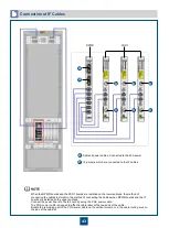
Page 19: ...16 Cable Connections c COA power interface F f cable a b a b COA power cable ...
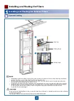
Page 36: ...33 Upward Cabling c Cable distribution plate To the alarm monitor SEI board ...
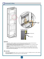
Page 37: ...34 Downward cabling d Cable distribution plate SEI board To the alarm monitor a a ...

