52
Check the current of the fuses for the power supply facilities.
Measure the voltage between NEG(-) and RTN(+) on the DC power distribution box.
Value Range of the Voltage
–48 V Power Supply
–60 V Power Supply
–38.4 V to –57.6 V
–48 V to –72 V
Do not power on the equipment if the input power voltage is beyond the specified range.
Subrack Type
Maximum Power
Consumption
Current of the Fuse
Standard OptiX OSN 2500
subrack
400 W
15 A
Enhanced OptiX OSN 2500
subrack
650 W
20 A
3
Checking the Subrack Power-on
Check the connection between the core end terminal of the power cable and the corresponding output terminal of the power
distribution box. Check if all power connectors are connected tightly. If not, use the flat-head screwdriver to tighten the captive
screws on the connectors of power cables.
Check the connection of the other end (with OT naked crimping connector) of the power cable with the PIU board. Each subrack
must be provided with two lines of power supply.
Turn on the power switch of the part A on the DC power distribution box for each subrack. Check if the subrack are powered on. If
powered on, go on turning on the power switch of the part B and then turn off the power switch of the part A. Check if the subrack
are powered on. If powered on, turn on the power switch of the part A.
Check the cabinet power indicator on the top of the cabinet. The green indicator stays on.
When the subrack is powered on, the fan starts to operate. Check the air ventilation at the top and the bottom of the subrack.
Observe the STATE indicator on the front panel of the fan. Normally, it is always green.
If the STATE indicator is constantly red, it indicates that the fan is faulty. In this case, replace the faulty fan.
If the STATE indicator is constantly yellow, it indicates that the fan is shut down automatically in case of low temperature.
If the STATE indicator is off, the fan is powered off or is not installed.
Do not insert or remove power plugs and the PIU when the power is on.
WARNING
Summary of Contents for OptiX OSN 2500
Page 1: ...HUAWEI TECHNOLOGIES CO LTD OptiX OSN 2500 Quick Installation Guide Issue 12 Date 2017 09 30 ...
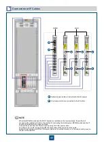
Page 19: ...16 Cable Connections c COA power interface F f cable a b a b COA power cable ...
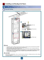
Page 36: ...33 Upward Cabling c Cable distribution plate To the alarm monitor SEI board ...
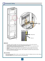
Page 37: ...34 Downward cabling d Cable distribution plate SEI board To the alarm monitor a a ...


