background image

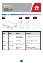
OT terminal

Battery

connecting kit

Bolt

Spring washer

Flat washer

2

2

Installing Equipment

Installing the iBAT

2.1

1. Open the battery string switch. Install iBAT 

cables on the battery.

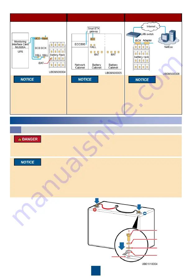
UPS scenario

ECC scenario

NetEco scenario

To ensure that the wireless 
communication signals are 
free from interference, the 
distance between the iBOX 
and the iBAT should be less 
than or equal to 15 m.

To ensure that the wireless 
communication signals 
between the iBOX and the 
iBAT are free from interference, 
remove adjacent side panels 
when combining multiple 
battery cabinets.

If the LAN switch in the 
equipment room provides a 
PoE port, no adapter is 
required.

• Voltages on the iBAT cables are hazardous. Therefore, wear insulation gloves when performing 

operations on the cables.

• The red terminal is positive, and the black terminal is negative. Connect battery terminals correctly.

• After the product is installed, if the battery is not charged for more than 30 days, you are advised 

to remove the iBAT from the battery cables.

• Torque: M6: 4–6 N·m M8: 13–15 N·m M10: 15–20 N·m.
• Ensure that terminals are visible when installing the iBAT. If you want to connect iBATs in parallel, 

install the iBATs after collecting iBAT SN information and installing cables.

• Do not power on the iBAT before connecting the battery to the system.
• Do not install the iBAT on the exhaust valve of the valve-regulated lead acid (VRLA) battery.

Summary of Contents for Hall

Page 1: ...n collection module One iBOX supports a maximum of 200 iBATs and manages iBATs for a maximum of four battery strings iBAT iBAT 12V 12 V battery monitoring module Supports 12 V power input and detects the voltages internal resistances and pole temperatures of batteries Adapter POE35 54A Power supply for the iBOX N A HALL N A Battery current detection One iBOX can connect to a maximum of eight Hall ...

Page 2: ...ent room provides a PoE port no adapter is required Voltages on the iBAT cables are hazardous Therefore wear insulation gloves when performing operations on the cables The red terminal is positive and the black terminal is negative Connect battery terminals correctly After the product is installed if the battery is not charged for more than 30 days you are advised to remove the iBAT from the batte...

Page 3: ...Installing Hall Effect Sensors 2 2 2 Insert the terminal into the iBAT port with force and ensure that it is securely connected 3 Attach the iBAT to the top or side of the battery based on the battery installation space Press the iBAT with your palm for more than 10 seconds to ensure that it is attached firmly and evenly With a neutral wire Cable Label iBOX Port Battery1 _HALL1 HALL_1 Battery1 _HA...

Page 4: ...ttery1_HALL2 HALL_2 Battery2_HALL3 HALL_3 Battery2_HALL4 HALL_4 Battery3_HALL5 HALL_5 Battery3_HALL6 HALL_6 Battery4_HALL7 HALL_7 Battery4_HALL8 HALL_8 Cable Label iBOX Port Battery1_HALL1 HALL_1 Battery2_HALL2 HALL_2 Battery3_HALL3 HALL_3 Battery4_HALL4 HALL_4 Without a neutral wire For cables with labels Hall Hall Hall_1 and Hall_2 connect the terminal labeled Hall to the positive Hall effect se...

Page 5: ...itioning frame of the fixing bracket press the fastener for more than 10 seconds and ensure that the fastener is attached firmly and evenly 4 Mount the iBOX onto the fastener and ensure that the iBOX is securely installed ECC scenario Installing an Adapter 2 4 Tapping screw Washer Plastic expansion sleeve Select a proper installation position for the adapter according to the actual layout Prepare ...

Page 6: ...t and COM port are connected to RJ45 straight through cables Prepare cables and terminals by yourself Pin PoE Port Pin Definition COM Port Pin Definition 1 TX RS485 2 TX RS485 3 RX NC 4 48V RS485 5 48V RS485 6 RX GND GND 7 48V NC 8 48V NC One UPS is configured with one iBOX to manage four battery strings ...

Page 7: ...PS is configured with four iBOXs to manage four battery strings respectively Set the iBOX DIP switches as shown in the figure The DIP switch addresses of iBOX 1 to iBOX 4 in the management system are 60 to 63 ...

Page 8: ...in the address box of Internet Explorer to log in to the iBOX WebUI homepage Logging In to the iBOX WebUI and Setting Parameters 3 2 5 On the iBOX WebUI Choose System Settings Battery Curve 6 On the Battery Curve page select the battery string to be set set Battery Brand and Format click Filter Submit Default iBOX settings IP address 192 168 0 10 Subnet mask 255 255 255 0 Gateway 192 168 0 1 User ...

Page 9: ... WebUI homepage MDU 3 On the UPS WebUI homepage choose Param Settings Battery Setting and set Number of battery strings 4 On the UPS WebUI homepage choose iBOX Settings and set Basic Param Advanced Param and Batt String Config Default UPS settings IP address 192 168 0 10 Subnet mask 255 255 255 0 Gateway 192 168 0 1 User Name admin Password Changeme NOTE If the BCB box is configured set Batt abnor...

Page 10: ...IB board The communications cable with an RJ45 connector delivered with the BCB box is used to connect the new BIB board and the cable without an RJ45 connector is used to connect the old BIB board This document describes the ECC800 as an example For details about the EIC800 refer to the ECC800 procedure NOTE BIB J1 iBOX BCB 5 OL OL 6 STA STA 7 DRV DRV 8 GND GND ...

Page 11: ...settings IP address 192 168 0 10 Subnet mask 255 255 255 0 Gateway 192 168 0 1 User Name admin Password Changeme 1 Use a straight through cable to connect the PC to the FE port on the ECC800 2 Enter https ECC800 IP address in the address box of Internet Explorer to log in to the ECC800 WebUI homepage 3 Choose Monitoring Power Distribution iBOXn Running Parameters set battery parameters by referrin...

Page 12: ...port on the adapter 3 Open Internet Explorer choose Tools Internet Options Advanced and ensure that Use TLS 1 1 and Use TLS 1 2 are selected 4 Enter https iBOX IP address in the address box of Internet Explorer to log in to the iBOX WebUI homepage Old BIB board New BIB board BIB J1 iBOX BCB 5 OL OL 6 STA STA 7 DRV DRV 8 GND GND BIB J1 iBOX BCB 5 OL OL 6 STA STA 7 DRV DRV 8 GND GND ...

Page 13: ...attery strings Indicates the total number of battery strings managed by the iBOX Batt string No Sets the battery string numbers of the iBOXs connected in parallel to unique ones when multiple iBOXs are connected in parallel 6 Access the System Settings Running parameter page and set Running parameter parameters according to the following table Running parameter Description Parallel Communication C...

Page 14: ...g page and select the site where the iBOX is located 3 Choose Device Battery Detector and drag the BMU icon to the creation area 4 On the Management Info pane set the Name IP Address Port and Connection Mode for the iBOX 5 Click Connection Test and save the setting after a message indicating successful connection appears IP address Must be the same as the iBOX IP address Port Set to 502 Connection...

Page 15: ...er than the value of iBAT number of iBOX Check that iBAT number of iBOX is set to a correct value and that the iBATs are successfully networked The RUN ALM indicator is blinking green at long intervals NOTE Serial Networking Parallel Networking 1 Check that the RF_Z indicators on all iBOXs are steady green Otherwise hold down the networking switch for 10 20s to clear the original network 2 Check t...

Page 16: ...ly connected in the parallel network when the RF_Z indicator on the iBOX turns from blinking green at super short intervals to blinking green at long intervals the networking is complete You can manually enter SN on the Service Expert app to collect the iBAT SN information Save the iBAT information file in CSV format It is recommended that the names of CSV files correspond to different iBOXs NOTE ...

Page 17: ... Installation of devices in the iBattery system All devices in the iBattery system are installed reliably Passed Failed 2 Labels of cables to the POE port COM port BCB port and HALL current detecting port on the iBattery system All cables for the iBattery system are connected correctly Both ends of a cable are labeled correctly and the labels provide concise and understandable cable description Pa...

Page 18: ...ternal resistance The iBAT is faulty Communication with the iBOX times out No network is connected The iBAT is waiting to connect to a network If an indicator blinks at long intervals it is blinking at 0 5 Hz that is on for 1s and then off for 1s If an indicator blinks at short intervals it is blinking at 4 Hz that is on for 0 125s and then off for 0 125s If an indicator blinks at super short inte...

Page 19: ... China www huawei com Scan here for more documents You can also log in to Huawei technical support website http support huawei com enterprise http support huawei com Support Support E WeChat Scan here for technical support enterprise Scan here for technical support carrier Huawei App Store Huawei App Store ...

Reviews: