background image

FusionModule1000A20 CT Solution 
Maintenance Guide 

3 Routine Maintenance 


Issue 01 (2019-02-25) 

Copyright © Huawei Technologies Co., Ltd. 

14 


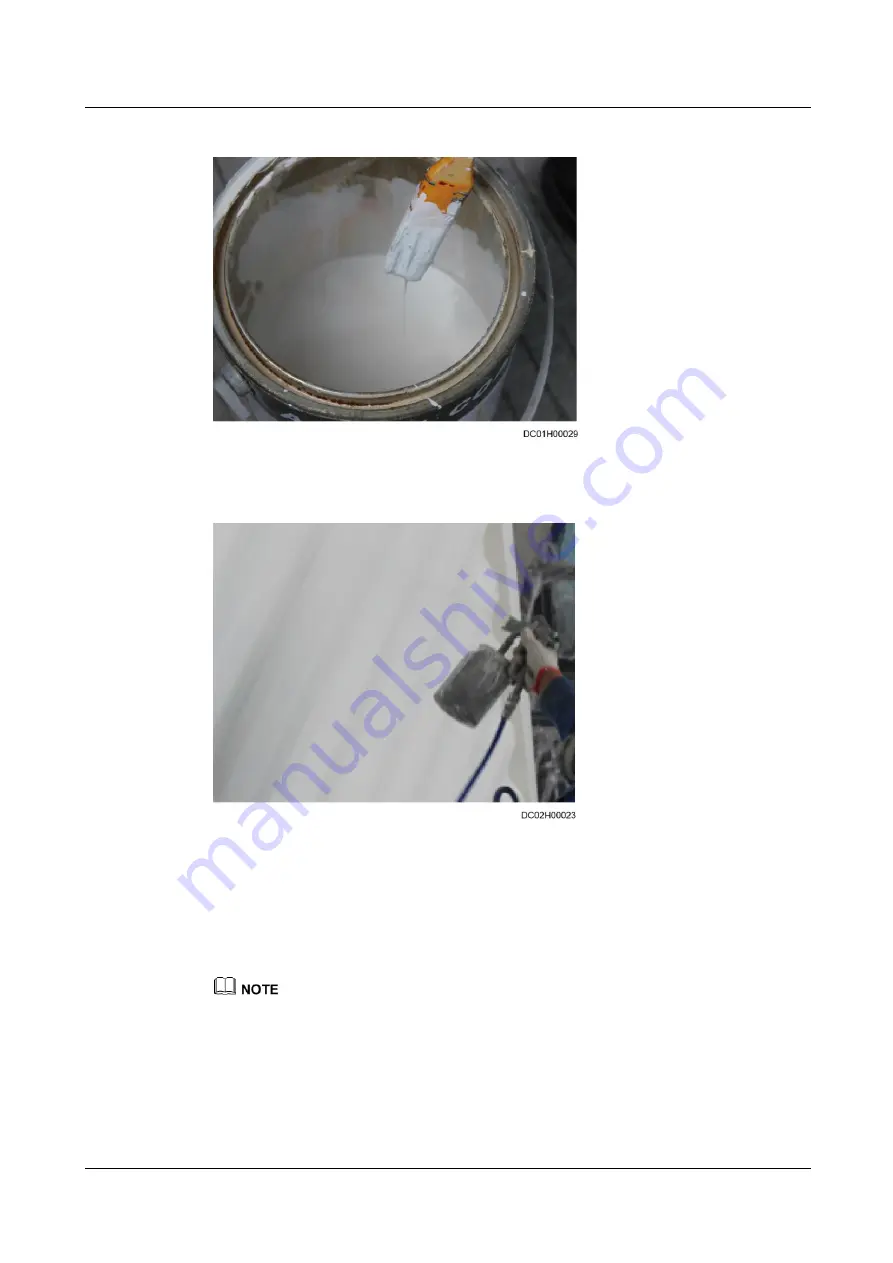
Figure 3-5


Repainting using a brush 


Figure 3-6


Repainting using a painting gun 


----End 

Follow-up Procedure 

Check whether the surface meets the requirement after repainting.   


The repainted area should have the same color as surrounding areas. The color difference δE is not 
greater than 3 (Use a colorimeter to measure the color difference. If a colorimeter is not available, check 
that no obvious edge exists between the repainted area and its surrounding.) The paint should also be 
free from bulges, scratches, flake-off, or cracks. 

Summary of Contents for FusionModule1000A20

Page 1: ...FusionModule1000A20 CT Solution V200R003C00 Maintenance Guide Issue 01 Date 2019 02 25 HUAWEI TECHNOLOGIES CO LTD ...

Page 2: ...stomer All or part of the products services and features described in this document may not be within the purchase scope or the usage scope Unless otherwise specified in the contract all statements information and recommendations in this document are provided AS IS without warranties guarantees or representations of any kind either express or implied The information in this document is subject to ...

Page 3: ...s of the FusionModule1000 Intended Audience This document is intended for Maintenance engineers Technical support engineers System engineers Hardware installation engineers Commissioning engineers Data configuration engineers Symbol Conventions The symbols that may be found in this document are defined as follows Symbol Remarks Indicates an imminently hazardous situation which if not avoided will ...

Page 4: ...ioration or unanticipated results NOTICE is used to address practices not related to personal injury Calls attention to important information best practices and tips NOTE is used to address information not related to personal injury equipment damage and environment deterioration Change History Changes between document issues are cumulative The latest document issue contains all updates made in pre...

Page 5: ...ng Compartment 15 3 3 Daily Maintenance 16 3 4 Monthly Maintenance 18 3 4 1 Power Supply and Distribution System 18 3 4 2 Cooling System 19 3 4 3 Monitoring System 22 3 4 4 Fire Extinguishing System CE 26 3 4 5 Other Systems 28 3 5 Quarterly Maintenance 29 3 5 1 Power Supply and Distribution System 29 3 5 2 Monitoring System 30 3 5 3 Fire Extinguishing System CE 36 3 5 4 Other Systems 36 3 6 Semi ...

Page 6: ... a Battery for the DC Power System 68 5 1 4 Replacing a Light 69 5 1 5 Replacing the Power PDB 70 5 2 Replacing Cooling System Components 71 5 2 1 Replacing Components for a 12 5 kW Fresh Air Integrated Unit 71 5 2 1 1 Replacing an Air Filter 71 5 2 1 2 Replacing an Air Damper 72 5 2 2 Optional Replacing a Low Temperature Component 73 5 2 3 Replacing an Air Vent Air Filter 74 5 2 4 Replacing a Hyd...

Page 7: ... 104 5 4 1 Replacing Fire Extinguishing System Devices CE 104 5 4 1 1 Replacing a Smoke Detector CE 104 5 4 1 2 Replacing a Heat Detector CE 105 5 4 1 3 Replacing Warning Signs CE 107 5 4 1 4 Replacing an Internal Horn Strobe CE 109 5 4 1 5 Replacing an External Horn Strobe CE 112 5 4 1 6 Replacing a Fire Alarm Bell CE 115 5 4 1 7 Replacing the Extinguishant Abort Button CE 117 5 4 1 8 Replacing B...

Page 8: ...generate electric arcs or sparks which may cause fire or hurt human eyes Before removing component cables mark the cables with their corresponding port numbers for later connection Before connecting a power cable check that the label on the power cable is correct For the detailed power control relationships between devices see the power distribution system diagram for the solution in use During ba...

Page 9: ...form O M for the management system Routine maintenance for the management system is critical for long term stable and efficient operation of the FusionModule1000 because most alarms are reported over the management system Promptly handle reported alarms to prevent equipment damage or service interruption Check and calibrate the hydrogen detection equipment sensors half a year within the sensor ser...

Page 10: ... Ltd 3 2 Operation and Maintenance Preparations 2 1 Tools Prepare tools listed in Table 2 1 before performing O M operations Table 2 1 Tools Tools Phillips screwdriver Flat head screwdriver Adjustable wrench Electrician s knife Needle nose pliers Diagonal pliers Crimping tool Wire stripper RJ45 crimping tool Cable cutter Hex key Socket wrench ...

Page 11: ...meter Electroprobe Network cable tester Heat gun Utility knife Step ladder 2 m Cable tie Insulation tape ESD wrist strap ESD gloves Protective gloves Clamp meter ESD floor suction plate Vacuum cleaner The listed tools are for routine maintenance only Prepare other tools as required 2 2 Obtaining Technical Documents Table 2 2 lists the technical documents required for FusionModule1000 O M ...

Page 12: ...ll in One Data Center V200R003C00 Installation Guide CT Provides detailed information on how to install the FusionModule1000 Download this document from http support huawei com Download this document from http e huawei com FusionModule1000A20 Prefabricated All in One Data Center V200R003C00 Commissioning Guide CT Describes how to commissioning for the FusionModule1000 Download this document from h...

Page 13: ...ftware The NetEco version depends on the version in use Click on the NetEco WebUI to obtain the NetEco version If the NetEco version is iManager NetEco V600R007C80 see iManager NetEco Product Document V600R007C80 for details Download this document from http support huawei com The NetEco version depends on the version in use Click on the NetEco WebUI to obtain the NetEco version If the NetEco versi...

Page 14: ...r Manual V600R007C80 for details Download this document from http support huawei com The NetEco version in use prevails Click the icon on the NetEco WebUI to obtain the information about the NetEco version If the NetEco version is iManager NetEco V600R007C80 see iManager NetEco PowerEcho User Manual V600R007C80 for details Download this document from http e huawei com 2 3 Container Entry Requireme...

Page 15: ...he items to be taken out Sign out Follow up Procedure Return the ESD clothes and shoes If any faulty component is replaced dispose of the removed faulty component Replace maintain and troubleshoot components of the FusionModule1000 only in the presence of qualified engineers 2 4 O M Personnel Skill Requirements Field Personnel Skill Requirement Power supply and distribution system Familiar with th...

Page 16: ...nel Skill Requirement Fire extinguishin g system Familiar with the fire extinguishing system configurations and the operations for each core component in the FusionModule1000 With fire engineer qualifications Lighting and structural system Familiar with the overall configurations and layout of the FusionModule1000 Experienced in maintaining the FusionModule1000 ...

Page 17: ...ontainer surface is bumped scratched or rusted the paint should be repaired Check the damage to the container paint and prepare appropriate tools and materials The number of materials depends on site requirements Table 3 1 Paint repair Paint Damage Tools and Materials Procedure Description Slight scratch steel base material not exposed Spray paint or paint brush required for repainting a small are...

Page 18: ... paint coating should be thin and even Paint drops are prohibited on the coating The surface should be smooth 5 Leave the repainted area for about 30 minutes before performing any further operation LOGO and pattern damage Seek help from Huawei headquarters for a detailed painting solution Frontline personnel can turn to local advertisement coating suppliers Dent 1 If a dent is less than 100 mm2 in...

Page 19: ...p 2 Dip a piece of cotton cloth into anhydrous alcohol and wipe the polished or damaged area to remove the dirt and dust Then wipe off the alcohol with a clean and dry cotton cloth as shown in Figure 3 2 Figure 3 2 Wiping a polished or damaged area using anhydrous alcohol Step 3 Paint one layer of zinc rich primer on the damaged coat using a brush or painting gun as shown in Figure 3 3 ...

Page 20: ... damage degree of the paint described in Table 3 1 using a spray bottle brush or painting gun respectively shown in Figure 3 4 Figure 3 5 and Figure 3 6 In the case that a container pattern has different colors to prevent undamaged areas and those with different colors as the damaged area from being polluted during repainting cover such areas using white paper and adhesive tape before repairing pa...

Page 21: ... Procedure Check whether the surface meets the requirement after repainting The repainted area should have the same color as surrounding areas The color difference δE is not greater than 3 Use a colorimeter to measure the color difference If a colorimeter is not available check that no obvious edge exists between the repainted area and its surrounding The paint should also be free from bulges scra...

Page 22: ...extinguishing compartment Before maintaining the fire cylinder you need to operate the shutter Procedure Step 1 Pull the beaded rope at the side of the shutter in the fire extinguishing compartment until all blades of the shutter are perpendicular to the guide rail at the top Figure 3 7 Rotating the shutter blades Step 2 Pull the rope at the side of the shutter in the fire extinguishing compartmen...

Page 23: ...Procedure After maintaining the fire cylinder restore the shutter by referring to the operations in Step 2 to Step 1 3 3 Daily Maintenance Table 3 2 Daily maintenance checklist Categ ory Mainten ance Item Operation Check Standard Troubleshooting Power Supply and Distrib TP48400 B Check whether the door lock is damaged The door lock is intact and working properly Replace the door lock ...

Page 24: ...cators are steady on If an indicator is off or dim replace it For details refer to 5 1 2 5 Replacing an Indicator Check the SPD indicator and SPD circuit breaker status The SPD indicator is green If the SPD indicator is red replace the SPD For details refer to 5 1 2 4 Replacing an SPD The SPD circuit breaker is switched to ON 1 If the SPD indicator is red replace the SPD For details refer to 5 1 2...

Page 25: ... coverage Fire extingu ishing system VESDA and its power supply Check the working status of the VESDA and its power supply The VESDA and its power supply are normal If the VESDA or its power supply is abnormal troubleshoot by following instructions in documents delivered with the VESDA 3 4 Monthly Maintenance 3 4 1 Power Supply and Distribution System Table 3 3 Monthly maintenance checklist for th...

Page 26: ...ltage is normal using a multimeter The battery low voltage disconnection BLVD or load low voltage disconnection LLVD voltage is inside the rated range Rectify the fault by referring to TP48200B N20B2 TP48200B N20B3 TP48200B L20B2 TP48400B N20B3 TP48400B L20B1 V500R002 User Manual Check whether the indicators are in normal status The indicators are normal Check whether the coating of the power syst...

Page 27: ... pressure tube is properly connected Verify that the pressure tube of the air filter clogging switch is fixed properly If the fault persists replace the differential pressure switch Indoor fan The fan enclosure is not misshapen Repair the enclosure Foreign matter does not exist in the fans Clear foreign matter The fan blades are intact For details contact Huawei technical support The indoor fan ge...

Page 28: ... contact Huawei technical support Optional Low temperature component Low temperature component The low temperature component is intact Replace by following instructions in 5 2 2 Optional Replacing a Low Temperature Component Hydrogen exhaust fan Check whether the hydrogen exhaust fan has stopped working is not rotating smoothly loosen or deformed using a flashlight The hydrogen fan is secure worki...

Page 29: ...ge range 43 58 V DC rated voltage 53 5 V DC If the input voltage is abnormal check the power grid and input cable connection Power output Voltage range 43 58 V DC rated voltage 53 5 V DC For details contact Huawei technical support Operating environment Temperature 20 C to 65 C Humidity 5 95 RH non condensing Check that the ambient temperature and humidity for the combined module are normal Access...

Page 30: ... 1s or registration with the ECC800 is successful Blinking at short interval The communication is interrupted or the registration with the ECC800 fails the indicator blinks at 4 Hz on for 0 125s and then off for 0 125s Blinking The indicator blinks at super short intervals for 0 5s blinking at 10 Hz on for 0 05s and then off for 0 05s and then turns off for 0 5s The cycle lasts for 10s Check the p...

Page 31: ...nd then off for 0 05s Blinking at super short intervals intermittently The device is searching for a network the indicator blinks at 2 Hz on for 0 5 and then off for 0 5s Refer to ECC800 Data Center Controller V100R001C30 User Manual to register the device or contact Huawei technical support Table 3 6 Monthly maintenance checklist for the monitoring system Check Item Operation Check Standard Troub...

Page 32: ...linking slowly The software runs properly the indicator blinks at 0 5 Hz on for 1s and then off for 1s or registration with the ECC800 is successful Blinking at short interval The communication is interrupted or the registration with the ECC800 fails the indicator blinks at 4 Hz on for 0 125s and then off for 0 125s Blinking The indicator blinks at super short intervals for 0 5s blinking at 10 Hz ...

Page 33: ...arching for a network the indicator blinks at 2 Hz on for 0 5 and then off for 0 5s Refer to ECC800 Data Center Controller V100R001C30 User Manual to register the device or contact Huawei technical support Pad Exterior The exterior is intact and the touchscreen is working properly Replace the pad Exit button Function The function is normal Replace by following instructions in 5 3 10 2 Replacing an...

Page 34: ...der CE For details about how to replace other devices contact Huawei technical support All devices of the fire extinguisher are free from rust on the exterior and the coating is intact Repaint The lead seal and safety signs on hand operated devices of the fire cylinder are intact Replace the electrical actuator Check the pressure pointer of the fire cylinder The pressure pointer is in the green zo...

Page 35: ...ff or rust by referring to 3 1 Container Repainting External environmen t of containers Check whether hazards or potential hazards exist around the containers No hazard or potential hazard exists around the containers Take measures to handle potential hazards Check whether obvious rubbish exists around the containers No obvious rubbish exists around the containers Clean the rubbish Check whether t...

Page 36: ...eaker is switched to ON Switch on the circuit breaker Push any button on the PD510 electricity meter LCD The PD510 electricity meter LCD lights up and displays information properly 1 If the LCD does not display information properly no display or fuzzy check whether the power cable is properly connected 2 If the power cable is correctly connected replace the PD510 by following instructions in 5 1 2...

Page 37: ...or Use a hand held thermohygrog raph to measure both the humidity and temperature in an aisle Compare the measured values with the values displayed on the sensor LCD The values measured are consistent with those displayed on the sensor LCD The temperature difference is within 2 C and the humidity difference within 5 RH If the differences exceed the allowed range replace by following instructions i...

Page 38: ... 1s or registration with the ECC800 is successful Blinking at short interval The communication is interrupted or the registration with the ECC800 fails the indicator blinks at 4 Hz on for 0 125s and then off for 0 125s Blinking The indicator blinks at super short intervals for 0 5s blinking at 10 Hz on for 0 05s and then off for 0 05s and then turns off for 0 5s The cycle lasts for 10s Check the p...

Page 39: ...hort intervals intermittently The device is searching for a network the indicator blinks at 2 Hz on for 0 5 and then off for 0 5s Refer to ECC800 Data Center Controller V100R001C30 User Manual to register the device or contact Huawei technical support AC actuator Power input Input voltage 90 240 V AC Check the input power cables if the input voltage is abnormal Power output Output voltage 90 240 V...

Page 40: ... 1s or registration with the ECC800 is successful Blinking at short interval The communication is interrupted or the registration with the ECC800 fails the indicator blinks at 4 Hz on for 0 125s and then off for 0 125s Blinking The indicator blinks at super short intervals for 0 5s blinking at 10 Hz on for 0 05s and then off for 0 05s and then turns off for 0 5s The cycle lasts for 10s Check the p...

Page 41: ...for 0 05s and then off for 0 05s Blinking at super short intervals intermittently The device is searching for a network the indicator blinks at 2 Hz on for 0 5 and then off for 0 5s Refer to ECC800 Data Center Controller V100R001C30 User Manual to register the device or contact Huawei technical support Table 3 11 Quarterly maintenance checklist for the monitoring system Check Item Operation Check ...

Page 42: ... ECC800 fails the indicator blinks at 4 Hz on for 0 125s and then off for 0 125s Check the power supply Refer to ECC800 Data Center Controller V100R001C30 User Manual to register the device or contact Huawei technical support WPS indicator On The WPS is working properly Blinking The WPS is in matching mode If the matching fails the WPS indicator turns off after blinking for 2 minutes If the matchi...

Page 43: ...l CE Hand held fire extinguishe r Check the hand held fire extinguisher The hand held fire extinguisher is in good condition Replace the hand held fire extinguisher The pressure pointer of the hand held fire extinguisher is in the green zone The fire extinguisher is within the validity period 3 5 4 Other Systems Table 3 13 Quarterly maintenance checklist for other systems Item Method Check Standar...

Page 44: ...t breaker is switched to ON Switch on the circuit breaker Push any button on the PD510 electricity meter LCD The PD510 electricity meter LCD lights up and displays information properly 1 If the LCD does not display information properly no display or fuzzy check whether the power cable is properly connected 2 If the power cable is correctly connected replace the PD510 by following instructions in 5...

Page 45: ... maintenance checklist for the cooling system Main tenan ce Item Operation Check Standard Troubleshooting Disch arge pipe Check the pressure at the needle valve of the discharge pipe Discharge pressure range Ambient temperature of 10 15 C 1 0 1 5 MPa Ambient temperature of 15 35 C 1 5 2 0 MPa Ambient temperature of 35 45 C 2 0 2 5 MPa See Alarms for the Cooling System Measures ambient temperatures...

Page 46: ...ts in the sight glass If you find air bubbles with the sight glass the cooling system lacks refrigerant Adjust the expansion valve or fill in refrigerant a The superheat degree is the saturation temperature minus the temperature where the sensing bulb is installed Measure the pressure at the needle valve for the suction pipe and find out the saturation temperature by using the measured pressure as...

Page 47: ...ks at super short intervals for 0 5s blinking at 10 Hz on for 0 05s and then off for 0 05s and then turns off for 0 5s The cycle lasts for 10s Check the power supply Refer to ECC800 Data Center Controller V100R001C30 User Manual to register the device or contact Huawei technical support ALM indicator Steady on A fault alarm is generated Off No fault alarm is generated Refer to ECC800 Data Center C...

Page 48: ...o the 2ND STAGE NO terminal on the extinguishant control panel to enable the linkage control function and inform the administrative departments that the system has become operational Before maintaining the fire extinguishing system remove the electrical actuator from the container valve of the fire cylinder This prevents the extinguishant release due to misoperations and prevents accidental damage...

Page 49: ...tch The warning sign indicator is on Replace by following instructions in 5 4 1 3 Replacing Warning Signs CE Heat detector Heat the heat detector using a heating device 1 If the temperature is below the alarm threshold the alarm indicator blinks once every 6s 2 If the temperature is above the alarm threshold the indicator turns on The extinguishant control panel generates an alarm and triggers the...

Page 50: ...erates glaring flashes and shrill alarms For details see 5 4 1 4 Replacing an Internal Horn Strobe CE or 5 4 1 5 Replacing an External Horn Strobe CE VESDA Check the VESDA sampling pipes The supports and connectors of the sampling pipes are securely connected Replace damaged sampling pipes and apply glue where pipes are not well sealed Remove or block a sampling pipe An alarm is generated See docu...

Page 51: ...contact with the light base but fails to turn on replace the light Ventilation vent air filter Check whether the filter is blocked The air filter is not blocked If an air filter is slightly blocked clean the air filter and reinstall it If more than 50 of the meshes are blocked replace the air filter Cable trays inside containers Check whether the cable trays are securely connected without damage o...

Page 52: ...ubleshooting Check whether cables are intact Cable jackets are free from damage or cracks No cable overheats due to overload and the loads are within the rated capacity of the cables the cables works only a very short time under overload situations The bend radius of cables meets requirement s The cable armor is intact Replace parts that do not meet requirements ...

Page 53: ...igh The rectifier input voltage is too low The ambient temperature is too high The rectifier is abnormal 1 Check whether the AC input voltage exceeds the upper threshold of the rectifier working voltage If yes rectify the power supply fault and then resume the power supply 2 Check whether the AC input voltage is below the lower threshold of the rectifier working voltage If yes rectify the power su...

Page 54: ...tact The rectifier is faulty 1 Check whether the rectifier is removed If yes reinstall it 2 If the rectifier is in position remove the rectifier and reinstall it 3 If the alarm still exists replace the rectifier BLVD Disconn ected Major An AC power failure occurs Batteries are manually disconnected The battery disconnection voltage is set too high on the SMU 1 Check whether an AC power failure occ...

Page 55: ...roperly set If no adjust it to a proper value 2 Check whether the AC input voltage exceeds the AC overvoltage alarm threshold 280 V AC by default If yes handle the AC input fault AC Under Volt Major The AC undervoltage alarm threshold is not set properly on the SMU The power grid is faulty 1 Check whether the AC undervoltage alarm threshold is properly set If no adjust it to a proper value 2 Check...

Page 56: ...no adjust it to a proper value 2 Check whether the system voltage is set too high in manual mode If yes confirm the reason and adjust the voltage to normal after the operation 3 Remove the rectifiers one by one and check whether the alarm is cleared If the alarm still exists reinstall the rectifier If the alarm is cleared replace the rectifier DC Under Volt Major An AC power failure occurs The DC ...

Page 57: ... The DC SPD detection cable is disconnected The DC SPD is faulty 1 Check whether the DC SPD detection cable is disconnected If yes reconnect the cable 2 Check whether the DC SPD detection cable is disconnected If no replace the DC SPD 4 2 Alarms for the Cooling System Fault Category Alarm Severity Possible Cause Operation Temperature sensor failure Major The temperature sensor is not properly conn...

Page 58: ...heat loss is higher than expected Check the heat loss and verify whether the indoor environment is properly sealed EEPROM error Major The storage device is faulty Reset to the default value and set the parameter again If the alarm persists contact Huawei technical support High pressure low pressure or no airflow Major The suction pressure or discharge pressure of the compressor is too high Check t...

Page 59: ...s Alarm Name Alarm Severity Possible Cause Solution RF_Z breakdown Major 1 The RF_Z software version is incorrect 2 The RF_Z function is unavailable 1 Upgrade the ECC800 software by following the upgrade guide 2 Refer to ECC800 Data Center Controller V100R001C30 User Manual to replace the ECC800 main control module Operation log full Informati on The storage space occupied by run logs has reached ...

Page 60: ...ate promptly and change the existing one NetEco certificate expired Major The NetEco certificate has expired Apply for a new network security certificate promptly and change the existing one AI DI_1 alarm Minor 1 The onsite condition triggers the alarm 2 The cable connection is unreliable 3 The sensor is faulty 1 Check and clear the onsite alarm 2 Check the sensor cable connection 3 Replace the fa...

Page 61: ... AI DI_5 high alarm AI DI_6 high alarm AI DI_1 low alarm Minor 1 The signal volume is below the lower threshold 2 The alarm threshold is inappropriate 3 The sensor is not securely connected 4 The sensor is faulty 1 Check that the signal volume is not below the lower threshold 2 Check that the alarm threshold is appropriate 3 Check the sensor cable connection 4 Replace the faulty sensor by followin...

Page 62: ...not connected properly 2 The 3G module is faulty 3 The 3G module is removed 1 Reconnect the PSU properly 2 Replace the 3G module 4 3 2 Access Actuator Alarms Alarm Name Alarm Severity Possible Cause Solution Illegal door opening Major The door is open but no card swiping or exit button pressing is detected Check that the power supply port of the magnetic lock is not short circuited Magnetic lock o...

Page 63: ... 4 Critical The wireless communication 802 15 4 is interrupted 1 Check that the wireless indicator on the access actuator is normal 2 Check whether other devices are disconnected from the PoE bus and connect the cables PoE communication failure Critical The PoE communications cable is loose 1 Check that the network cable indicator on the access actuator is normal 2 Replace the PoE communications c...

Page 64: ...th power supply pin is short circuited 1 Check that the fourth output is not overloaded 2 Check that the fourth power supply pin is not short circuited Communication failure Critical The PoE communication is interrupted Check that cables are correctly connected for the smart ETH gateway and that the RUN indicator of the smart ETH gateway is blinking normally 4 3 4 AC Actuator Alarms Alarm Name Ala...

Page 65: ...l support Relay 2 Life Alarm Minor The use duration for relay 2 reaches the alarm threshold Replace the AC actuator Load fault Minor The load is damaged or not connected Check that the load is connected and in good condition Light on Warning The light is on for more than 100 minutes Check that the light is turned off in a timely manner 4 3 5 WiFi Converter Alarms Device Name Alarm Name Alarm Sever...

Page 66: ...air conditioner parts replacement the system may need to be powered off Take measures to prevent device overheating Table 5 1 lists the components that can be replaced for the power supply and distribution system Table 5 1 Components that can be replaced for the power supply and distribution system Device Component Name Reference Document DC power system TP48400B Rectifier TP48200B N20B2 TP48200B ...

Page 67: ...p ladder Materials spare ATS controller Documents documents delivered with the PDC power supply and distribution device layout diagram Skill requirement power distribution engineer For the table see the initial configuration parameter manual for the solution in use Procedure Step 1 Open the front door of the PDC turn off the input and output switches in the PDC and turn off the upstream and downst...

Page 68: ...he PDC Step 8 Check that the new ATS controller is working properly After power on the Power indicator of the controller lights up Step 9 Switch on downstream circuit breakers of the PDC End 5 1 2 2 Replacing an MCB Prerequisites A spare MCB of the same model is available and functional The PDC switch must be turned off Ensure that the power input is disconnected during replacement Impact on the S...

Page 69: ... remove the cable from the bottom of the MCB first After removing cables insulate the cable terminals When removing cables label the cables with corresponding terminal ports for later connection Step 5 Push the buckle at the MCB outwards using a flat head screwdriver and remove the faulty MCB Step 6 Install the new MCB by referring to the preceding method connect cables and tighten screws Step 7 R...

Page 70: ...ently press the latch outwards to remove the terminal block Step 4 Remove the faulty PD510 electricity meter and install a new PD510 electricity meter and insert the latch Step 5 Install the removed terminal block and ensure that the terminal block is connected properly Step 6 Optional Install the panel of the PD510 electricity meter Step 7 Configure the address and baud rate of the PD510 by refer...

Page 71: ... SPD Documents PDC user manual Skill requirement electrician s work permit Procedure Step 1 Remove the protective panel of the SPD Avoid touching any charged body when removing the panel Step 2 Switch off the SPD circuit breaker Step 3 Detect the L1 L2 L3 and N voltages to the PE using an electrical tester pen and verify that the faulty SPD has no voltage before replacing the faulty SPD Figure 5 2...

Page 72: ...tall the spare SPD module and switch on the SPD circuit breaker Step 6 Reinstall the protective panel End Follow up Procedure Dispose of the removed SPD module that is confirmed faulty 5 1 2 5 Replacing an Indicator Prerequisites An indicator is dim or faulty Spare indicators of the same model are available and functional Impact on the System None Preparations Tools Phillips screwdriver multimeter...

Page 73: ...sponding terminal ports for later connection Step 4 Remove the retaining ring from the indicator and remove the indicator from the mounting hole Step 5 Install a new indicator on the mounting hole secure the retaining ring reconnect the conducting wire and switch on the MCB End Follow up Procedure Dispose of the removed indicator that is confirmed faulty 5 1 2 6 Replacing a Fuse Prerequisites A sp...

Page 74: ...it Procedure Step 1 Shake the fuse terminal block gently pull it out and push it outwards The fuse position in the figure is for reference only The actual position prevails Figure 5 5 Removing the fuse terminal block Step 2 Remove the blown fuse and install a new one Step 3 Reinstall the fuse terminal block in the PDC Step 4 Check whether the new fuse works properly End Follow up Procedure Dispose...

Page 75: ...its cables Step 2 Install the spare T H sensor in the same way For details about how to install an ambient T H sensor see TP482000B N20B1 TP482000B N20B2 TP481200B N20B1 TP481200B N20B2 V300R002 Installation Guide End Follow up Procedure Dispose of the removed ambient T H sensor that is confirmed faulty 5 1 3 Replacing a Battery for the DC Power System Prerequisites A spare battery of the same mod...

Page 76: ...t of the battery rack Ensure human safety during the movement Step 5 Install the new battery and connect cables correctly based on the DC power system battery wiring diagram Step 6 Verify the battery connections Ensure that the battery quantity and cable connections comply with the design and the cables or copper bars are reliably installed Step 7 Switch on the circuit breaker of the battery in th...

Page 77: ...rodes Step 4 Install the new light in the original position End Follow up Procedure Dispose of the removed light that is confirmed faulty 5 1 5 Replacing the Power PDB Prerequisites A spare power PDB of the same model is available and functional Impact on the System None Preparations Tools Phillips screwdriver socket wrench Materials spare power PDB Documents power supply and distribution system d...

Page 78: ...r of the same model is available and functional If the condition allows switch off the power supply to the fresh air integrated unit Impact on the System The fresh air integrated unit is powered off the temperature inside the container may become too high affecting device operation Preparations Tools Phillips screwdriver protective gloves Materials spare air filter Documents documents delivered wi...

Page 79: ...needs to be replaced A spare air damper of the same model is available and functional Impact on the System The fresh air integrated unit is powered off the temperature inside the container may become too high affecting device operation Preparations Tools Phillips screwdriver Material spare air damper Documents none Skill requirement common technician Procedure Step 1 Open the air damper baffle pla...

Page 80: ...r damper in the original position End Follow up Procedure Dispose of the removed air damper that is confirmed faulty 5 2 2 Optional Replacing a Low Temperature Component Prerequisites A spare low temperature component of the same model is available and functional Impact on the System None Preparations Tools flat head screwdriver Materials spare low temperature component Documents cooling device in...

Page 81: ...de panel End Follow up Procedure Dispose of the removed low temperature component that is confirmed faulty 5 2 3 Replacing an Air Vent Air Filter Prerequisites An air vent air filter needs to be replaced A spare air vent air filter of the same model is available and functional Impact on the System None Preparations Tools Phillips screwdriver Materials spare air vent air filter Documents none Skill...

Page 82: ... the removed air vent air filter that is confirmed faulty 5 2 4 Replacing a Hydrogen Exhaust Fan Prerequisites A hydrogen exhaust fan needs to be replaced A spare hydrogen exhaust fan of the same model is available and functional Impact on the System None Preparations Tools Phillips screwdriver cable cutter insulation tape step ladder protective gloves Material quick connect terminals spare hydrog...

Page 83: ... the quick connect terminal when cutting the power cable to the hydrogen exhaust fan Step 3 Bind the reserved segment of the power cable for the hydrogen exhaust fan to the main line using insulation tape to avoid dangers Step 4 Remove the cover of the hydrogen exhaust fan using a Phillips screwdriver Step 5 Remove the screws securing the hydrogen exhaust fan using a Phillips screwdriver Figure 5 ...

Page 84: ... Module Prerequisites A spare ECC800 main control module of the same model is available and functional The ECC800 main control module is hot swappable Before disconnecting cables from the ECC800 main control module label the cables based on the corresponding ports Impact on the System None Preparations Tools ESD wrist strap ESD gloves Phillips screwdriver label marker Material spare ECC800 main co...

Page 85: ...e of the removed ECC800 main control module that is confirmed faulty 5 3 2 Replacing an ECC800 PSU CT Prerequisites A spare ECC800 PSU of the same model is available and functional A PSU is hot swappable Do not touch the terminals in the rear of a removed PSU to avoid electric shocks Impact on the System The ECC800 may be powered off Preparations Tools insulation gloves Materials spare ECC800 PSU ...

Page 86: ...e Dispose of the removed ECC800 PSU that is confirmed faulty 5 3 3 Replacing an AI DI Module Prerequisites A spare AI DI module of the same model is available and functional Impact on the System Components connected to the AI DI module may generate false alarms Preparations Tools Phillips screwdriver flat head screwdriver Materials spare AI DI module insulation tape Documents management system ini...

Page 87: ...p 2 Remove the faulty AI DI module from the cabinet Step 3 Install a new AI DI module on the rack Figure 5 11 Installing an AI DI module Step 4 Connect cables to the new AI DI module Step 5 Configure the AI DI module based on the management system initial configuration table End Follow up Procedure Dispose of the removed AI DI module that is confirmed faulty 5 3 4 Replacing a Smart ETH Gateway Pre...

Page 88: ...h Step 4 Install the spare smart ETH gateway in the original position and connect the cables End Follow up Procedure Dispose of the removed ETH gateway that is confirmed faulty 5 3 5 Replacing a Camera Prerequisites A spare camera of the same model is available and functional Impact on the System Video surveillance stops Preparations Tools Phillips screwdriver step ladder protective gloves Materia...

Page 89: ...t Huawei Technologies Co Ltd 82 Figure 5 12 Removing screws securing the transparent cover Step 2 Use a Phillips screwdriver to remove the screws that fasten the camera to its base Figure 5 13 Removing screws that secure the camera to its base Step 3 Remove the network cable and take out the camera ...

Page 90: ...w camera is working properly End Follow up Procedure Dispose of the removed camera that is confirmed faulty 5 3 6 Replacing an External Camera Prerequisites A spare external camera of the same model is available and functional Impact on the System None Preparations Tools Phillips screwdriver 1 and 2 Material spare external camera Documents documents delivered with the external camera external came...

Page 91: ...ites A spare signal SPD of the same model is available and functional Impact on the System None Preparations Tool Phillips screwdriver Materials signal SPD Documents signal SPD installation position diagram Skill requirement electrician s work permit For the diagram see the quick installation guide for the solution in use Procedure Step 1 Determine the position for installing the signal SPD based ...

Page 92: ...5 Copyright Huawei Technologies Co Ltd 85 Figure 5 14 Removing the signal SPD Step 3 Remove cables connected to the faulty signal SPD and remove the faulty signal SPD Step 4 Install the spare signal SPD and reconnect the cables in the same way Step 5 Reinstall the signal SPD clamping plate ...

Page 93: ... door of the SPD box End Follow up Procedure Dispose of the removed signal SPD that is confirmed faulty 5 3 8 Replacing an SD Card Prerequisites A spare SD card of the same model is available and functional Impact on the System None Preparations Tools camera screwdriver Materials spare SD card Documents monitoring device layout diagram Skill requirement extra low voltage ELV engineer ...

Page 94: ...ws on the front cover of the camera remove the front cover and take out the inner cover over the lens Figure 5 16 Removing the front and inner covers Step 2 Remove the faulty SD card from the SD card slot Step 3 Insert a new SD card into the SD card slot Figure 5 17 Installing an SD card Step 4 Reinstall the inner and front covers End Follow up Procedure Dispose of the removed SD card that is conf...

Page 95: ...ture sensor Documents monitoring device layout management system initial configuration table Skill requirement weak current engineer For the diagrams and tables see the initial configuration parameter manual for the solution in use Procedure Step 1 Locate the water sensor to be replaced based on the alarm information on the monitoring software terminal Figure 5 18 shows a point type water sensor F...

Page 96: ...e new water sensor is working properly Drip a small amount of water onto the water sensor If the monitoring software terminal generates an alarm the water sensor is working properly End Follow up Procedure Dispose of the removed water sensor that is confirmed faulty 5 3 10 Replacing Access Control Components 5 3 10 1 Replacing an IC Card Reader Prerequisites An IC card reader needs to be replaced ...

Page 97: ...e door of the IC cared reader box Step 2 Remove the two screws from the bottom of the IC card reader and remove the front cover Figure 5 20 Removing the front cover Step 3 Remove the two screws that secure the IC card reader body Figure 5 21 Removing screws Step 4 Remove interconnection terminals from the IC card reader and remove the IC card reader body Step 5 Remove the two screws from the botto...

Page 98: ... operations are logged in the monitoring system End Follow up Procedure Dispose of the removed IC card reader that is confirmed faulty 5 3 10 2 Replacing an Exit Button Prerequisites An exit button needs to be replaced A spare exit button of the same model is available and functional Impact on the System None Preparations Tools insulation tape Phillips screwdriver small sized flat head screwdriver...

Page 99: ... the new exit button is working properly If the container door can be opened using the exit button and the door opening event is logged the new exit button is working properly End Follow up Procedure Dispose of the removed exit button that is confirmed faulty 5 3 10 3 Replacing a Magnetic Lock Prerequisites The magnetic lock needs to be replaced A spare magnetic lock of the same model is available...

Page 100: ...ill requirement weak current engineer Procedure Step 1 Use a Phillips screwdriver to loosen screws from the baffle plate of the magnetic lock as shown by 1 in Figure 5 23 Figure 5 23 Removing screws Step 2 Remove cables connected to the magnetic lock Step 3 Use a 3 mm hex key to loosen screws from the baffle plate of the magnetic lock as shown by 2 and 3 in Figure 5 23 Step 4 Replace the magnetic ...

Page 101: ...End Follow up Procedure Dispose of the removed magnetic lock that is confirmed faulty 5 3 10 4 Replacing an Emergency Door Release Button Prerequisites The emergency door release button needs to be replaced A spare emergency door release button of the same model is available and functional Impact on the System None Preparations Tools insulation tape step ladder 2 m Phillips screwdriver protective ...

Page 102: ...5 25 Removing the emergency door release button Step 2 Install a new emergency door release button 1 Connect cables 2 Tighten screws on the base as shown by 1 in Figure 5 26 3 Install the glass panel as shown by 2 and 3 in Figure 5 26 4 Tighten screws as shown by 4 in Figure 5 26 Figure 5 26 Installing the emergency door release button Step 3 Check that the new emergency door release button is wor...

Page 103: ...ker Materials spare access actuator Documents none Skill requirement extra low voltage ELV engineer Procedure Step 1 Label each cable based on the corresponding ports on the access actuator Step 2 Disconnect cables from the access actuator Step 3 Remove the faulty access actuator from guide rails Step 4 Install the spare access actuator in the original position and connect the cables End Follow up...

Page 104: ...edure Step 1 Open the container door where the door status sensor to be replaced is installed Obtain permission from the related administration department before opening a container door Step 2 Open the door status sensor box and disconnect the cable to remove the door status sensor to be replaced Figure 5 27 Replacing a door status sensor Step 3 Install a new door status sensor and reconnect the ...

Page 105: ... system initial configuration table Skill requirement extra low voltage ELV engineer For the diagrams and tables see the initial configuration parameter manual for the solution in use Procedure Step 1 Press the clamp strip and remove the cover of the T H sensor Figure 5 28 Removing the T H sensor cover Step 2 Remove the network cable from the T H sensor Install a new T H sensor and reconnect the n...

Page 106: ...l requirement extra low voltage ELV engineer Procedure Step 1 Switch off the upstream AC input circuit breaker for the AC actuator Step 2 Label each cable based on the corresponding ports on the AC actuator Step 3 Open the cover on the front panel of the AC actuator and disconnect the cables Step 4 Remove the faulty AC actuator Step 5 Install the spare AC actuator in the original position and conn...

Page 107: ...i converter from the guide rails Step 4 Install the spare WiFi converter in the original position and connect the cables and antenna Step 5 Log in to the ECC800 WebUI choose System Settings WiFi Management enable the WiFi function and set the WiFi SSID and password according to the customer plan Step 6 Check that the app can be connected properly End Follow up Procedure Dispose of the removed WiFi...

Page 108: ...nal Replacing a CIM Prerequisites A spare CIM of the same model is available and functional Impact on the System None Preparations Tool Phillips screwdriver Materials spare CIM Documents iBAT 2 0 CIM01C2 User Manual Skill requirement extra low voltage ELV engineer Procedure Step 1 Clear the network parameters for all the BIMs managed by the CIM to be replaced If the CIM is damaged manually clear t...

Page 109: ...e cable labels Step 8 After installing the CIM network the CIM and BIM For details see the description about power on commissioning in the iBAT 2 0 CIM01C2 User Manual End Follow up Procedure Dispose of the removed CIM that is confirmed faulty 5 3 16 Removing a Camera SPD Module Prerequisites A spare camera SPD module of the same model is available and functional Context An SPD module consists of ...

Page 110: ...and pipeline technicians For the diagram see the quick installation guide for the solution in use Procedure Step 1 Move the SLPU and UFLP to the specified installation position based on the peripheral monitoring device installation position diagram Step 2 Remove screws securing the UFLP and remove it from the SLPU slot Step 3 Remove screws securing the SLPU and take the SLPU out of the cabinet Ste...

Page 111: ...Document fire extinguishing device layout diagram CE Skill requirement fire engineer For the diagrams see the initial configuration parameter manual for the solution in use Before replacing the smoke detector inform the related administrative departments of the temporary downtime of the fire extinguishing system In addition remove the cable connected to the 2ND STAGE NO terminal on the extinguisha...

Page 112: ...nect the resistor to the new smoke detector when you replace the smoke detector Step 4 Remove the screws on the base using a Phillips screwdriver and remove the base Step 5 Install the new base to the same position and reconnect the cables Step 6 Insert the new smoke detector into the base and rotate it clockwise until it locks in Step 7 Switch on the input circuit breaker of the extinguishant con...

Page 113: ...the related administrative departments of the temporary downtime of the fire extinguishing system In addition remove the cable connected to the 2ND STAGE NO terminal on the extinguishant control panel to disable the linkage control function After the heat detector is replaced reconnect the cable to the 2ND STAGE NO terminal on the extinguishant control panel to enable the linkage control function ...

Page 114: ...ove the base Step 5 Install the new base to the same position and reconnect the cables Step 6 Insert the new heat detector into the base and rotate it clockwise until it locks in Step 7 Switch on the input circuit breaker of the extinguishant control panel and connect the cables to the battery Step 8 Check whether the new heat detector is working properly If the red indicator blinks once every 6s ...

Page 115: ...of the fire extinguishing system In addition remove the cable connected to the 2ND STAGE NO terminal on the extinguishant control panel to disable the linkage control function After the warning signs indicator is replaced reconnect the cable to the 2ND STAGE NO terminal on the extinguishant control panel to enable the linkage control function and inform the administrative departments that the syst...

Page 116: ...icator is working properly 1 Pull up the reset button on the pneumatic switch to short circuit the cables within to simulate a warning sign If the warning sign turns on the warning sign is working properly 2 Press the reset button on the pneumatic switch 3 Flip the key to Enable Control counterclockwise rightward Reset the extinguishant control panel by pressing Reset on it Then reset key to Enabl...

Page 117: ...ng system In addition remove the cable connected to the 2ND STAGE NO terminal on the extinguishant control panel to disable the linkage control function After the horn strobe is replaced reconnect the cable to the 2ND STAGE NO terminal on the extinguishant control panel to enable the linkage control function and inform the administrative departments that the system has become operational Figure 5 ...

Page 118: ...robe in the loop in parallel remove the terminal resistor from the faulty horn strobe and connect the resistor to the new horn strobe when you replace the horn strobe Figure 5 40 Removing cables from the horn strobe Step 4 Remove screws from the horn strobe base using a Phillips screwdriver and remove the base Step 5 Install the new horn strobe in the same way connect the cables and install the co...

Page 119: ... works properly 3 Reset the manual gas release button 4 Flip the key to Enable Control counterclockwise rightward Reset the extinguishant control panel by pressing Reset on it Then reset key to Enable Control clockwise leftward End Follow up Procedure Dispose of the removed horn strobe that is confirmed faulty 5 4 1 5 Replacing an External Horn Strobe CE Prerequisites A spare horn strobe is availa...

Page 120: ...uishant control panel to disable the linkage control function After the horn strobe is replaced reconnect the cable to the 2ND STAGE NO terminal on the extinguishant control panel to enable the linkage control function and inform the administrative departments that the system has become operational Figure 5 41 Position of the 2ND STAGE NO terminal Procedure Step 1 Disconnect the battery cables and...

Page 121: ...cover Step 6 Switch on the input circuit breaker of the extinguishant control panel and connect the battery cables Step 7 Check that the new horn strobe is working properly 1 Disconnect the wiring terminals from the electrical actuator on the fire cylinder After the wiring terminals are disconnected from the electrical actuator the extinguishant control panel generates an alarm which is normal 2 P...

Page 122: ...nitial configuration parameter manual for the solution in use Before replacing the fire alarm bell inform the related administrative departments of the temporary downtime of the fire extinguishing system In addition remove the cable connected to the 2ND STAGE NO terminal on the extinguishant control panel to disable the linkage control function After the fire alarm bell is replaced reconnect the c...

Page 123: ...e fire alarm bell base using a Phillips screwdriver and remove the base Step 5 Install the new base in the same way connect the cables and install the cover Step 6 Switch on the input circuit breaker of the extinguishant control panel and connect the battery cables Step 7 Check whether the new fire alarm bell is working properly 1 Flip the key to Enable Control rightward and set the access level o...

Page 124: ...tial configuration parameter manual for the solution in use Before replacing the extinguishant abort button inform the related administrative departments of the temporary downtime of the fire extinguishing system In addition remove the cable connected to the 2ND STAGE NO terminal on the extinguishant control panel to disable the linkage control function After the extinguishant abort button is repl...

Page 125: ...les from the extinguishant abort button and remove the panel of the extinguishant abort button Figure 5 48 Disconnecting cables from the extinguishant abort button As a resistor is installed on the loop of the extinguishant abort button remove the resistor and connect the resistor to the corresponding terminals of the new extinguishant abort button when you replace the extinguishant abort button S...

Page 126: ...erminals Step 7 Install the new extinguishant abort button panel in the same way Figure 5 50 Installing the extinguishant abort button Step 8 Switch on the input circuit breaker of the extinguishant control panel and connect the battery cables Step 9 Check whether the new extinguishant abort button is working properly 1 Disconnect the wiring terminals from the electrical actuator on the fire cylin...

Page 127: ... leftward End Follow up Procedure Dispose of the removed the extinguishant abort button that is confirmed faulty 5 4 1 8 Replacing Batteries for the Extinguishant Control Panel CE Prerequisites Spare extinguishant control panel batteries of the same model are available and functional Impact on the System None Preparations Tools protective gloves step ladder Materials spare extinguishant control pa...

Page 128: ...ed extinguishant control panel batteries that are confirmed faulty 5 4 1 9 Replacing a Fire Cylinder CE Prerequisites A spare fire cylinder of the same model is available and functional Impact on the System The fire extinguishing system stops working during the replacement Preparations Tools pipe wrench pallet truck Phillips screwdriver adjustable wrench protective gloves Materials spare fire cyli...

Page 129: ...perational Figure 5 52 Position of the 2ND STAGE NO terminal Procedure Step 1 Disconnect the battery cables and switch off the input circuit breaker of the extinguishant control panel Step 2 Move the new fire cylinder using a pallet truck to a position adjacent to the container door Do not impact or strike the fire cylinder during transportation or installation Assign sufficient people for transpo...

Page 130: ...tighten the straps Keep the pressure gauge panel outwards so that people can view the reading Step 9 Connect the hose to the pneumatic switch Wrap the threads with sealing tape to ensure air tightness Step 10 Connect the fire cylinder to the fire extinguishing pipeline Wrap the threads with sealing tape to ensure air tightness 1 Connect the threaded adapter to the fire cylinder 2 Connect the I sha...

Page 131: ...tor 2 Align the electrical actuator and the container valve and tighten the actuator clockwise Step 12 Connect the interconnection terminals on the electrical actuator to the extinguishant control panel Step 13 Switch on the input circuit breaker of the extinguishant control panel and connect the battery cables to power on the panel End Follow up Procedure Dispose of the removed fire cylinder that...

Page 132: ...to disable the linkage control function After the extinguishant control panel is replaced reconnect the cable to the 2ND STAGE NO terminal on the extinguishant control panel to enable the linkage control function and inform the administrative departments that the system has become operational Figure 5 55 Position of the 2ND STAGE NO terminal Procedure Step 1 Switch off the input circuit breaker on...

Page 133: ...h on the input circuit breaker of the extinguishant control panel and connect the battery cables Step 10 Check whether the new extinguishant control panel is working properly If the power indicator is on and the alarm indicator is off the fire control panel is working properly End Follow up Procedure Dispose of the removed extinguishant control panel that is confirmed faulty 5 4 1 11 Replacing an ...

Page 134: ...er plug of the emergency light Figure 5 57 Removing the power plug Step 2 Remove the protective cover of the emergency light Step 3 Loosen the emergency panel using a flat head screwdriver and remove the panel Step 4 Remove screws from the emergency light base using a Phillips screwdriver and remove the base Step 5 Install the new emergency light base and the panel in the same way Step 6 Remove th...

Page 135: ...for the VESDA Power Box Prerequisites Spare VESDA power box batteries of the same model are available and functional Impact on the System None Preparations Tools Phillips screwdriver protective gloves Materials spare VESDA power box batteries Documents fire extinguishing device layout diagram standard Skill requirement fire engineer For the diagrams see the initial configuration parameter manual f...

Page 136: ...Disconnect cables from the faulty VESDA batteries Step 4 Use a Phillips screwdriver to remove screws on the battery protective panel and remove the protective panel Step 5 Replace the batteries and connect battery cables Distinguish the positive and negative battery terminals when connecting battery cables Figure 5 60 Connecting battery cables Step 6 Reinstall the battery protective panel ...

Page 137: ...d 130 Figure 5 61 Installing the battery protective panel Step 7 Check whether the new VESDA batteries are working properly Turn on the standby power switch If the power fault indicator is off the batteries are working properly End Follow up Procedure Dispose of the removed VESDA power box batteries that are confirmed faulty ...

Page 138: ... 25 Copyright Huawei Technologies Co Ltd 131 6 FusionModule1000 Emergency Exit Guide If an emergency occurs push open the nearest pre fab module door shown in the emergency exit diagram with force as shown in Figure 6 1 Then exit from the pre fab module immediately Figure 6 1 Opening the emergency exit door ...

Page 139: ...2 7 Acronyms and Abbreviations A AC Alternating Current ATS automatic transfer switch C CAN control area network CE Conformite Europende D DDF digital distribution frame E ECC energy control center L LCD liquid crystal display M MDU monitor display module P PoE power over Ethernet PDC power distribution cabinet PDU power distribution unit ...

Page 140: ...ronyms and Abbreviations Issue 01 2019 02 25 Copyright Huawei Technologies Co Ltd 133 R rPDU rack power distribution unit S SIM subscriber identity module U UPS uninterruptible power system V VCN video cloud node VESDA very early smoke detection apparatus ...

Reviews: