background image

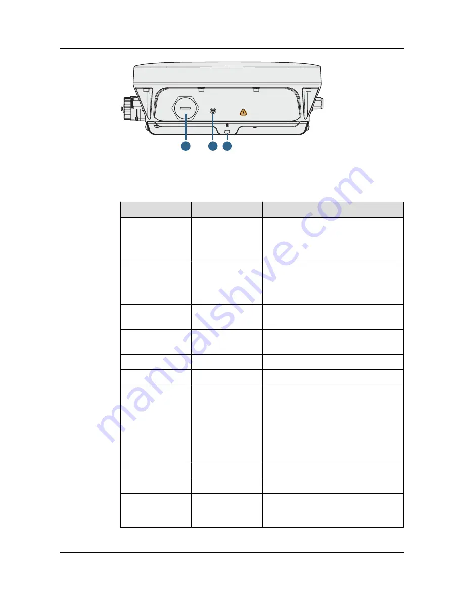
Console

Default

6

7

8

Table 1-1

 describes interfaces on the AP8030DN and AP8130DN.

Table 1-1

 Descriptions of interfaces

No.

Name

Description

1

GE0/PoE

10/100/1000M bit/s interface: connects to the
wired Ethernet. The interface can connect to
a PoE power supply to provide power for the
AP.

2

GE1

10/100/1000M bit/s interface: connects to the
wired Ethernet. The interface can't connect to
a PoE power supply to provide power for the
AP.

3

SFP

Connects an optical fiber to the AP. An
optical module must be installed first.

4

5 GHz antenna
interface

Connects a 5 GHz antenna to the AP.

5

2.4G/5G

2.4 GHz or 5 GHz antenna interface.

6

Console

Console: Console interface

7

Default

Reset button: restores factory settings and
restarts the AP if you hold down the Reset
button for more than 3 seconds.

NOTE

The Reset button is protected by a waterproof
screw. Before pressing the Reset button, remove
the waterproof screw. Keep the screw properly and
install it again after pressing the Reset button.

8

Security slot

Connects to a security lock.

9

Device ground screw Connects a ground cable to the AP.

10

Ground screw for the
surge protective
device

Connects the AP to the ground point of an
external surge protective device.


Huawei AP8030DN & AP8130DN
Hardware Installation and Maintenance Guide

1 AP8130DN & AP8030DN Overview

Issue 02 (2014-12-05)

Huawei Proprietary and Confidential

Copyright © Huawei Technologies Co., Ltd.

3

Summary of Contents for AP8030DN

Page 1: ...Huawei AP8030DN AP8130DN Hardware Installation and Maintenance Guide Issue 02 Date 2014 12 05 HUAWEI TECHNOLOGIES CO LTD ...

Page 2: ...t may not be within the purchase scope or the usage scope Unless otherwise specified in the contract all statements information and recommendations in this document are provided AS IS without warranties guarantees or representations of any kind either express or implied The information in this document is subject to change without notice Every effort has been made in the preparation of this docume...

Page 3: ...n which if not avoided will result in death or serious injury Indicates a potentially hazardous situation which if not avoided could result in death or serious injury Indicates a potentially hazardous situation which if not avoided may result in minor or moderate injury Indicates a potentially hazardous situation which if not avoided could result in equipment damage data loss performance deteriora...

Page 4: ...s all changes made in previous issues Issue 02 2014 12 05 This version has the following updates The following information is modified l Installation of the angle adjusting component with AP8030DN is added The following information is added l 1 4 Ordering Information Issue 01 2014 08 20 Initial commercial release Huawei AP8030DN AP8130DN Hardware Installation and Maintenance Guide About This Docum...

Page 5: ...etwork Cables 26 2 6 3 Connecting Ground Cables 28 2 6 4 Installing Outdoor Antennas 31 2 7 Installing the Security Lock 33 2 8 Checking the AP After Installation 34 2 9 Powering on the AP 34 3 Logging In to the AP 35 3 1 Logging In to the AP Through the Console Port 36 3 2 Logging In to the AP Using STelnet 36 3 3 Logging In to the AP Using Telnet 38 3 4 Logging In to the AP Using a Web Client 38...

Page 6: ...pment Room 97 5 3 3 Grounding Specifications for Devices 97 5 3 4 Grounding Specifications for Communications Power Supply 98 5 3 5 Grounding Specifications for Signal Cables 99 5 3 6 Specifications for Laying Out Grounding Cables 99 5 4 Engineering Labels for Cables 100 5 4 1 Introduction to Labels 100 5 4 2 Engineering Labels for Optical Fibers 108 5 4 3 Engineering Labels for Network Cables 111...

Page 7: ... deployment automatic AC discovery and configuration and real time management and maintenance which meets requirements of outdoor deployment Huawei AP8030DNs and AP8130DNs comply with IP67 dustproof and waterproof protection standards applicable to coverage scenarios for example squares pedestrian streets and amusement parks and bridging scenarios for example wireless harbors data backhaul video s...

Page 8: ...nk ACT2 1 3 2 9 Consol e Def aul t 6 7 8 Figure 1 2 AP8130DN appearance 5G GE0 PoE GE1 SFP SYS 2 4G 5G Link ACT1 Wireless1 Link ACT0 Wireless0 Link ACT2 1 3 2 4 5 10 9 10 2 4G 5G 2 4G 5G 5G 5G 5 4 10 Huawei AP8030DN AP8130DN Hardware Installation and Maintenance Guide 1 AP8130DN AP8030DN Overview Issue 02 2014 12 05 Huawei Proprietary and Confidential Copyright Huawei Technologies Co Ltd 2 ...

Page 9: ...5 GHz antenna interface 6 Console Console Console interface 7 Default Reset button restores factory settings and restarts the AP if you hold down the Reset button for more than 3 seconds NOTE The Reset button is protected by a waterproof screw Before pressing the Reset button remove the waterproof screw Keep the screw properly and install it again after pressing the Reset button 8 Security slot Co...

Page 10: ...1 SYS Li nk ACT1 W i rel ess1 Li nk ACT0 W i rel ess0 Li nk ACT2 SYS indicator Table 1 2 Descriptions about the SYS indicator Type Color Status Description Default status after power on Green Steady on The AP is just powered on and the software is not started yet Software startup status Green Steady on after blinking once After the system is reset and starts uploading the software the indicator bl...

Page 11: ...omatically rectified and must be rectified manually Link ACT indicators Link ACT indicators consist of Link ACT0 Link ACT1 and Link ACT2 showing link status of interfaces GE0 PoE GE1 SFP respectively Table 1 3 Descriptions about the Link ACT indicators Type Color Status Description LINK Green Steady on The system is running properly the Ethernet connection is normal and no data is being transmitte...

Page 12: ...TAs connected to both the 2 4 GHz radio and 5 GHz radio The indicator blinks more quickly when more data is being transmitted Table 1 5 Wireless bridge indicator Color Status Description Yellow green Off The AP is not transmitting or receiving data or the signal strength is extremely low Blinking once every 2s 0 5 Hz The AP is transmitting or receiving data normally and the signal strength is low ...

Page 13: ...eless LED reflects the weakest signal strength of middle APs l wifi light traffic allows the Wireless LED to reflect the service traffic volume on the radio The Fat AP does not support WDS Mesh functions therefore the Wireless indicator of the Fat AP does not indicate the signal strength 1 3 Basic Specifications Table 1 6 and Table 1 7 provides basic specifications of the AP8030DN and AP8130DN Tab...

Page 14: ...er consumption depends on local laws and regulations Environment specifications Operating temperature 60 m to 1800 m 40 C to 60 C 1800 m to 5000 m Temperature decreases by 1 C every time the altitude increases 220 m Storage temperature 40 C to 70 C Operating humidity 0 to 100 non condensing IP rating IP67 Atmospheric pressure 53 kPa to 106 kPa 1 4 Ordering Information To place an order contact the...

Page 15: ...Built in Antenna 02359462 Assembling Components AP8130DN AP8130DN AP8130DN Mainframe 11ac General AP Outdoor 3x3 Double Frequency External Antenna Huawei AP8030DN AP8130DN Hardware Installation and Maintenance Guide 1 AP8130DN AP8030DN Overview Issue 02 2014 12 05 Huawei Proprietary and Confidential Copyright Huawei Technologies Co Ltd 9 ...

Page 16: ...Installation Position 2 5 Installing the AP 2 6 Connecting Cables 2 7 Installing the Security Lock 2 8 Checking the AP After Installation 2 9 Powering on the AP Huawei AP8030DN AP8130DN Hardware Installation and Maintenance Guide 2 AP Installation Issue 02 2014 12 05 Huawei Proprietary and Confidential Copyright Huawei Technologies Co Ltd 10 ...

Page 17: ...alified personnel are permitted to install and remove the device and its accessories Before installation and operation read the safety precautions carefully Tool Preparation To install the APs prepare tools listed in Table 2 1 Table 2 1 Tools Phillips screwdriver M4 Torque screwdriver 3mm 5mm M3 M6 Torque socket M6 Hammer drill φ8 Utility knife Cable cutter Diagonal pliers RJ45 crimping tool Wire ...

Page 18: ... Torque wrench Use an N type open end torque wrench 2 2 Installation Flowchart Figure 2 1 shows the flowchart for installing an AP8130DN Huawei AP8030DN AP8130DN Hardware Installation and Maintenance Guide 2 AP Installation Issue 02 2014 12 05 Huawei Proprietary and Confidential Copyright Huawei Technologies Co Ltd 12 ...

Page 19: ...e packing carton is intact and not damaged or soaked Stop unpacking if the equipment is rusted or soggy Then investigate causes and contact the supplier After unpacking check items in the carton against the packing list If any item is missing contact the supplier or agent Usually the packing carton contains all items listed in the packing list shown in Table 2 2 Table 2 2 Packing list No Item Quan...

Page 20: ... free from leaking or dripping water heavy dew and humidity and take protective measures to prevent water from flowing into the equipment along the cable l Install the AP in a hidden position that does not affect daily lives and work of residents l Make the engineering design by fully considering such factors as hydrology geology earthquake electric power and traffic The selected site should compl...

Page 21: ... 6 3 6 6 LQN 7 LUHOHVV LQN 7 LUHOHVV LQN 7 260 290 The AP8030DN and AP8130DN have the same space requirements Figure 2 4 shows space requirements for installing an AP8130DN Huawei AP8030DN AP8130DN Hardware Installation and Maintenance Guide 2 AP Installation Issue 02 2014 12 05 Huawei Proprietary and Confidential Copyright Huawei Technologies Co Ltd 15 ...

Page 22: ...gle adjusting component is required The procedures are as follows 1 Fix the mounting bracket to the wall adjust the installation position and use the marker to mark the drilling positions where expansion bolts are installed See the following figure for the installation positions Huawei AP8030DN AP8130DN Hardware Installation and Maintenance Guide 2 AP Installation Issue 02 2014 12 05 Huawei Propri...

Page 23: ...until the flat washers are completely attached to the wall Then remove the nut spring washer and flat washer in order 90DŽ Ø8 35mm 40mm a b 1 2 3 3 Use four M4x12 hexagon socket head cap screws to fasten the AP side module of the mounting bracket to the AP Huawei AP8030DN AP8130DN Hardware Installation and Maintenance Guide 2 AP Installation Issue 02 2014 12 05 Huawei Proprietary and Confidential C...

Page 24: ...tallation requires use of the angle adjusting component but the AP8130DN does not Install the AP8030DN a Hang the angle adjusting component on the mounting bracket and use a Phillips screwdriver to tighten the screw at position 3 with a tightening torque of 1 4N m Huawei AP8030DN AP8130DN Hardware Installation and Maintenance Guide 2 AP Installation Issue 02 2014 12 05 Huawei Proprietary and Confi...

Page 25: ...l angle of the AP use the M6 hex key to remove the screw at position 2 lift the angle adjusting component vertically and adjust the angle adjusting component horizontally Huawei AP8030DN AP8130DN Hardware Installation and Maintenance Guide 2 AP Installation Issue 02 2014 12 05 Huawei Proprietary and Confidential Copyright Huawei Technologies Co Ltd 19 ...

Page 26: ...ll side mounting bracket module and tighten the screws to secure the AP Install the AP8130DN a Hang the AP with the AP side mounting bracket module to the wall side mounting bracket module and tighten the screws to secure the AP HIDXOW 1 2 1N m M4 Huawei AP8030DN AP8130DN Hardware Installation and Maintenance Guide 2 AP Installation Issue 02 2014 12 05 Huawei Proprietary and Confidential Copyright...

Page 27: ... d Use the hex torque screwdriver to tighten the screws with a torque of 5 N m 5N m M6 a b c d 2 Install the AP The AP8030DN installation requires use of the angle adjusting component but the AP8130DN does not Install the AP8030DN a Hang the angle adjusting component on the mounting bracket and use a Phillips screwdriver to tighten the screw at position 3 with a tightening torque of 1 4N m Huawei ...

Page 28: ...l angle of the AP use the M6 hex key to remove the screw at position 2 lift the angle adjusting component vertically and adjust the angle adjusting component horizontally Huawei AP8030DN AP8130DN Hardware Installation and Maintenance Guide 2 AP Installation Issue 02 2014 12 05 Huawei Proprietary and Confidential Copyright Huawei Technologies Co Ltd 22 ...

Page 29: ...ll side mounting bracket module and tighten the screws to secure the AP Install the AP8130DN a Hang the AP with the AP side mounting bracket module to the wall side mounting bracket module and tighten the screws to secure the AP HIDXOW 1 2 1N m M4 Huawei AP8030DN AP8130DN Hardware Installation and Maintenance Guide 2 AP Installation Issue 02 2014 12 05 Huawei Proprietary and Confidential Copyright...

Page 30: ... 2 4G 5G 2 4G 5G 5G 5G D ef aul t 2 6 Connecting Cables Figure 2 5 AP8130DN external cable arrangement Feed line Feed line Feed line Feed line Feed line Feed line Optical fiber Network cable Huawei AP8030DN AP8130DN Hardware Installation and Maintenance Guide 2 AP Installation Issue 02 2014 12 05 Huawei Proprietary and Confidential Copyright Huawei Technologies Co Ltd 24 ...

Page 31: ...then from bottom to top l Bend radius requirements RG 8U RF cable 150 mm 1 2 RF cable 50 mm 7 8 RF cable 250 mm One inch equals to 25 4 mm NOTICE Tighten the nut of the AP s RF connector with a maximum torque of 1 2 N m RF cable connections 1 Antenna interfaces of the AP provides a 5 KA surge protection capability Generally no additional surge protective device needs to be installed and the RF cab...

Page 32: ...r according to the figure 2 When connecting an optical fiber to the AP loosen the device side fiber connector put the optical fiber through the fiber connector and tighten the fiber connector on the device according to the figure Huawei AP8030DN AP8130DN Hardware Installation and Maintenance Guide 2 AP Installation Issue 02 2014 12 05 Huawei Proprietary and Confidential Copyright Huawei Technologi...

Page 33: ...even if devices can be connected Table 2 3 Pin assignment X1 Pin Wire Color X2 Pin 1 White and orange 1 2 Orange 2 3 White and green 3 4 Blue 4 5 White and blue 5 6 Green 6 7 White and brown 7 8 Brown 8 NOTE Actually APs use shielded straight through network cables which are connected in the same way as unshielded network cables 3 Put the network cable through waterproof PG connectors Connect the ...

Page 34: ...ground cables must be connected to a group of ground bars l The bend radius of the ground cables must be larger than or equal to five times the cable diameter l The ground cables must be buried underground or routed indoors and cannot be led into the equipment room aerially l Both ends of the external conductor of the coaxial cable and those of the shield layer of the shielded cable should have go...

Page 35: ...bles can improve surge protection performance of the AP To connect the cable cut the shield layer open connect the cable to the ground clip and wrap the cable with waterproof and ESD tapes 1 Determine the position for installing the ground clip on the cable based on the actual cable route 2 Use a utility knife to strip the sheath off the network cable for about 32 mm 1 26in to expose the shield la...

Page 36: ...n and finally from bottom up Do not cut the tape until all the three layers of the tape are already wrapped When wrapping tape be sure that each layer of tape overlaps more than 50 of the preceding layer l The degree between the ground cable and the network cable cable is not greater than 15 When the network cable is routed vertically the ground cable must be routed downwards Huawei AP8030DN AP813...

Page 37: ... pole vertical to the ground during the installation See Figure 2 6 below for how a directional outdoor antenna is installed on a pole l If the roof of the building is surrounded by parapets of no less than 1 2 m high fix the pole on a parapet with expansion screws and then fix the directional outdoor antenna on the pole with an antenna support l If the roof of the building is surrounded by parape...

Page 38: ...th a diameter of 30 mm to 50 mm and the thickness must be at least 2 5 mm A 50 mm diameter pole made of round steel is usually used 2 The top of pole must be aligned with the hose clamp at the bottom of the antenna 3 The antenna must be installed at a proper height to provide sufficient signal coverage and the top of the antenna must be within the 45 degrees protection angle of the lighting rod 4 ...

Page 39: ...s a steel pole you do not need to install a lightening rod as shown on the right in Figure 2 8 2 7 Installing the Security Lock There is a security slot on the AP You can lock the AP to an immovable object to prevent the AP against theft The detailed procedures are as follows 1 Fasten the cable of the security lock to an immovable object around 2 Insert the security lock into the security slot and...

Page 40: ...t short circuited or reversely connected and must be intact with no damage 7 The power cables and ground cables are separated from other cables and bundled separately 8 The working ground protection ground and surge protection ground share the same group of ground bars 9 Connectors of signal cables are complete intact and tightly connected The signal cables are not damaged or broken 10 Labels on c...

Page 41: ...V200R005C00 and later versions Disable Enable 3 1 Logging In to the AP Through the Console Port 3 2 Logging In to the AP Using STelnet 3 3 Logging In to the AP Using Telnet 3 4 Logging In to the AP Using a Web Client Huawei AP8030DN AP8130DN Hardware Installation and Maintenance Guide 3 Logging In to the AP Issue 02 2014 12 05 Huawei Proprietary and Confidential Copyright Huawei Technologies Co Lt...

Page 42: ... the AP Enter a question mark whenever you need help 3 2 Logging In to the AP Using STelnet This section describes how to log in to the AP using STelnet After logging in to the AP you can configure the AP using commands Before logging in to the device through STelnet complete the following tasks l Starting the device properly l Preparing network cables used to connect device interfaces NOTE Ensuri...

Page 43: ...ddress and select the SSH protocol type Figure 3 1 PuTTY Configuration page 3 Click Open Enter the user name and password at the prompt and press Enter You have logged in to the device The following information is only for reference login as admin Sent username admin admin 169 254 1 1 s password Huawei NOTE It is recommended that you change the initial user name and password after login Huawei AP8...

Page 44: ...fo id ap id command to check the AP s IP address 3 Enter the command line interface on the PC For example in Windows XP choose Start Run and enter cmd in the displayed dialog box 4 Use Telnet to log in to the AP 5 Enter the default user name and password The default user name is admin and the default password is admin huawei com If the user view is displayed you have logged in successfully You are...

Page 45: ...C and enter the management address in the format of http 169 254 1 1 in the address bar Ensure that the PC and AC can communicate with each other Then press Enter Set the language user name and password The HTTPS login URL is displayed in the address box indicating that the system has gone to the HTTPS login page NOTE You can also enter https IP address in the address box to log in to the AP using...

Page 46: ...oting typical hardware faults 4 1 An device Fails to Be Powered On 4 2 An Optical Interface Cannot Turn Up Huawei AP8030DN AP8130DN Hardware Installation and Maintenance Guide 4 Hardware Failures Issue 02 2014 12 05 Huawei Proprietary and Confidential Copyright Huawei Technologies Co Ltd 40 ...

Page 47: ...r adapter 4 If the device still cannot be powered on the device itself is faulty Contact Huawei technical support or Huawei agent through Hotline Email and ask them to replace the device 4 2 An Optical Interface Cannot Turn Up Fault Description After an optical interface is connected to a remote device through an optical fiber its LINK indicator is off Possible Causes l The optical fiber is faulty...

Page 48: ... power is too high The high transmit power may even burn the receiver of the remote optical module To reduce the transmit power in this situation use an optical attenuator between the optical module and optical fiber l Optical modules with different speeds are available for example 155 Mbit s 622 Mbit s and 1 25 Gbit s It is recommended that you use an optical module with the same speed as the opt...

Page 49: ...vice Operation 5 3 Equipment Grounding Specifications 5 4 Engineering Labels for Cables 5 5 Guide to Using Optical Modules 5 6 Fault Tag Huawei AP8030DN AP8130DN Hardware Installation and Maintenance Guide 5 Appendix Issue 02 2014 12 05 Huawei Proprietary and Confidential Copyright Huawei Technologies Co Ltd 43 ...

Page 50: ...red by Huawei and follow the methods given here during assembly l Hold terminals of cables instead of pulling the cables when installing or removing cable components l Take the following precautions when cutting or stripping cables Make cables slightly longer than necessary Coil cables longer than 2 m 6 56 ft after cutting Bind and fasten the coils using bundling ropes The inner diameters of the c...

Page 51: ...l and Power Cable Context Figure 5 1 shows the components of an OT terminal and a power cable Figure 5 1 Components of an OT terminal and a power cable A Heat shrinkable tubing B Bare crimping terminal C Insulation D Conductor Procedure Step 1 Based on the cross sectional area of the cable conductor strip a length of insulation coating C to expose the conductor D of length L1 as shown in Figure 5 ...

Page 52: ...f Conductor mm2 in 2 Value of L1 mm in 1 0 002 7 0 28 10 0 015 11 0 43 1 5 0 002 7 0 28 16 0 025 13 0 51 2 5 0 004 7 0 28 25 0 039 14 0 55 4 0 006 8 0 31 35 0 054 16 0 63 6 0 009 9 0 35 50 0 077 16 0 63 NOTE If you are proficient in assembling OT terminals and power cables you can obtain the value of L1 by comparing the part to be crimped with the power cable Step 2 Put the heat shrinkable A tubin...

Page 53: ...of the conductor or L2 in Figure 5 3 must not be longer than 2 mm 0 08 in Step 4 Crimp the joint parts of the bare crimping terminal and the conductor as shown in Figure 5 4 NOTE The shapes of crimped parts may vary with the crimping dies Figure 5 4 Crimping the joint parts of the bare crimping terminal and the conductor OT terminal Huawei AP8030DN AP8130DN Hardware Installation and Maintenance Gu...

Page 54: ... heat the shrink tubing too long to damage the insulation coating End Assembling the JG Terminal and Power Cable Context Figure 5 6 shows the components of a JG terminal and a power cable Figure 5 6 Components of a JG terminal and a power cable A JG terminal B Heat shrinkable tube C Insulation layer of a power cable D Conductor of a power cable Huawei AP8030DN AP8130DN Hardware Installation and Ma...

Page 55: ...ust the value of L as required Figure 5 7 Stripping a power cable JG terminal Table 5 2 Mapping between the cross sectional area of the conductor and the value of L Cross Sectional Area of Conductor mm2 in 2 Value of L mm in 16 0 025 13 0 51 25 0 039 14 0 55 35 0 054 16 0 63 50 0 077 16 0 63 Step 2 Put the heat shrink tubing onto the bare crimping terminal as shown in Figure 5 8 Huawei AP8030DN AP...

Page 56: ... the conductor as shown in Figure 5 9 Figure 5 9 Crimping the joint parts of the bare crimping terminal and the conductor JG terminal Step 5 Push the heat shrink tubing towards the connector until the tube covers the crimped part and then heat the tube by using a heat gun as shown in Figure 5 10 Figure 5 10 Heating the heat shrink tubing JG terminal Huawei AP8030DN AP8130DN Hardware Installation a...

Page 57: ...1 Based on the cross sectional area of the cable conductor strip a part of the insulation The L1 long conductor is exposed as shown in Figure 5 12 The recommended values of L1 are listed in Table 5 3 NOTICE When you strip a power cable do not damage the conductor of the cable Figure 5 12 Stripping a power cable cord end terminal Huawei AP8030DN AP8130DN Hardware Installation and Maintenance Guide ...

Page 58: ...d end terminal onto the conductor and ensure that the conductor is aligned with the edge of the cord end terminal as shown in Figure 5 13 NOTICE After the conductor is fed into the cord end terminal the protruding part of the conductor must not be longer than 1 mm 0 04 in Figure 5 13 Put the cord end terminal onto the conductor Step 3 Crimp the joint parts of the cord end terminal and the conducto...

Page 59: ...um Width of Crimped Terminal W1 mm in 0 25 0 0004 1 0 04 0 5 0 0008 1 0 04 1 0 0 0015 1 5 0 06 1 5 0 0023 1 5 0 06 2 5 0 0039 2 4 0 09 4 0 006 3 1 0 12 6 0 009 4 0 16 10 0 015 5 3 0 21 16 0 025 6 0 24 25 0 039 8 7 0 34 35 0 054 10 0 39 End 5 1 3 Assembling Ethernet Cables Assembling the Shielded RJ45 Connector and Ethernet Cable Huawei AP8030DN AP8130DN Hardware Installation and Maintenance Guide ...

Page 60: ...rocedure Step 1 Fit the jacket of the connector onto the Ethernet cable as shown in Figure 5 16 Figure 5 16 Fit the jacket of the connector onto the Ethernet cable Step 2 Remove a 30 mm 1 18 in long section of the jacket cut off the nylon twine inside the jacket and cut a no more than 5 mm 0 20 in cleft in the jacket as shown in Figure 5 17 Huawei AP8030DN AP8130DN Hardware Installation and Mainte...

Page 61: ...as shown in Figure 5 18 Figure 5 18 Fitting the metal shell onto the twisted pair cable Step 4 Fit the metal shell onto the twisted pair cable until the shield layer is covered completely Along the edge of the metal shell cut off the aluminum foil shield layer and ensure that there is no surplus copper wire The exposed twisted pair cable is about 20 mm 0 79 in long as shown in Figure 5 19 Huawei A...

Page 62: ...igure 5 21 Cable locations in a wire holder White Green Green White Orange Orange Blue White Blue White Brown Brown Step 6 Align the four pairs of cables in the holder as shown in Figure 5 22 The connections between the wires and the pins are shown in Figure 5 23 and listed in Table 5 5 Huawei AP8030DN AP8130DN Hardware Installation and Maintenance Guide 5 Appendix Issue 02 2014 12 05 Huawei Propr...

Page 63: ...1 Table 5 5 Connections between wires and pins using a straight through cable as an example Matching Pins of Wires Wire Color 1 White Orange 2 Orange 3 White Green 4 Blue 5 White Blue 6 Green 7 White Brown Huawei AP8030DN AP8130DN Hardware Installation and Maintenance Guide 5 Appendix Issue 02 2014 12 05 Huawei Proprietary and Confidential Copyright Huawei Technologies Co Ltd 57 ...

Page 64: ... 5 25 NOTE Ensure that the wire holder is in good contact with the connector body Figure 5 25 Put the connector body onto the wire holder Step 9 Push the metal shell towards the connector body until the wire holder and the connector body are engaged completely Crimp the connector as shown in Figure 5 26 Huawei AP8030DN AP8130DN Hardware Installation and Maintenance Guide 5 Appendix Issue 02 2014 1...

Page 65: ...e metal shell Step 11 To complete the assembly of the other end repeat Step 1 through Step 10 End Assembling an Unshielded RJ45 Connector and Ethernet Cable Context Figure 5 28 shows the components of an unshielded RJ45 connector and cable Huawei AP8030DN AP8130DN Hardware Installation and Maintenance Guide 5 Appendix Issue 02 2014 12 05 Huawei Proprietary and Confidential Copyright Huawei Technol...

Page 66: ...ng the jacket of a twisted pair cable unit mm in Step 2 Align the four pairs of wires and cut the ends neatly as shown in Figure 5 30 The connections between the wires and the pins are listed in Table 5 6 Figure 5 30 Connections between wires and pins unit mm in C 16 White Orange White Green Orange Blue White Blue Green White Brown Brown Pin 8 Pin 1 Huawei AP8030DN AP8130DN Hardware Installation a...

Page 67: ...he plug to ensure that the cable is completely seated in the plug Figure 5 31 Crimping the connector Step 4 To complete the assembly of the other end repeat Step 1 through Step 3 End Checking the Appearance of Contact Strips Context l To ensure proper contact between the crimped wires and the wire conductors the heights and sizes of the contact strips must be standard and the same Huawei AP8030DN ...

Page 68: ...e between them must be less than 0 5 mm 0 02 in Procedure Step 1 Hold the crimped connector with the front side facing you and check whether the contact strips are of the same height The height should be 6 02 0 13 mm 0 237 0 005 If a measuring tool is not available you can compare the connector with a standard connector Figure 5 32 shows an unqualified piece and Figure 5 33 shows a qualified piece...

Page 69: ...w RJ45 connector Figure 5 35 shows an unqualified piece Figure 5 35 Dirt on a contract strip Step 4 Check whether the contact strips and the plastic separators are well aligned and intact If a separator is skew and cannot be fixed replace it with a new RJ45 connector Figure 5 36 shows an unqualified piece Figure 5 36 Skew plastic separators Huawei AP8030DN AP8130DN Hardware Installation and Mainte...

Page 70: ...thernet cables straight through cables and crossover cables l Straight through cables are connected in a one to one manner They are used to connect terminals such as a computer or switch to network devices Table 5 7 lists the connections of core wires in a straight through cable Table 5 7 Connections of core wires in a straight through cable RJ45 Connector 1 RJ45 Connector 2 Core Wire Color Twiste...

Page 71: ...s of an RJ45 connector Figure 5 38 Pins of an RJ45 connector Pin8 Pin1 Procedure Step 1 Feed both connectors of the cable into the ports of the cable tester Step 2 After the connectors are properly inserted turn on the tester If the indicators from 1 to G turn on simultaneously you can infer that the pins work normally and the wires are correctly connected NOTE Turn the switch to the S position to...

Page 72: ...uence in which the indicators turn on You need to refer to the wire connections of a crossover cable The Ethernet cable is qualified if the indicators turn on in the following sequence At the master left section of the tester the indicators turn on in the sequence of 1 8 G At the slave right section of the tester the indicators turn on in the sequence of 3 6 1 4 5 2 7 8 G Otherwise the Ethernet ca...

Page 73: ...faces In the actual situation the adapters may have interfaces fixed on equipment Use dedicated tools provided or specified by Huawei and follow the installation procedure described here Bending Radius Unless otherwise specified bending radiuses R of cables or fibers must meet the requirements listed in Table 5 9 Table 5 9 Bending radiuses of cables or fibers Cable or Fiber Bending Radius R Ordina...

Page 74: ... pliers such as cable pulling pliers and fiber pulling pliers l Do not twist bend stretch or extrude fibers during installation l Cover the fiber connectors that are not in use by using dustproof caps Remove the dustproof caps before using the fiber connectors Requirements for Cable Routing l To protect cables remove the burrs in the cable through holes or install protective rings in the holes l T...

Page 75: ...ve is installed as shown in Figure 5 43 where A is correct and B is wrong Figure 5 43 Installing an OT terminal showing the orientation of crimping sleeve 2 Place the spring washer and flat washer in turn mount a matching screw and fasten it clockwise as shown in Figure 5 44 Huawei AP8030DN AP8130DN Hardware Installation and Maintenance Guide 5 Appendix Issue 02 2014 12 05 Huawei Proprietary and C...

Page 76: ...tall two OT terminals on a post ensure that the two terminals can be installed on the post and that the electrical connecting pieces have a large contact area Two OT terminals can be installed using any of these methods Bend the upper OT terminal at a 45 or 90 degree angle as shown in Figure 5 46 Cross the two terminals as shown in Figure 5 47 Huawei AP8030DN AP8130DN Hardware Installation and Mai...

Page 77: ... terminal loosen the screw in the counterclockwise direction End Installing the Cord End Terminal Procedure Step 1 Hold a cord end terminal upright and place it on a terminal jack as shown in Figure 5 48 To ensure bump contact and dense connection place the plain side of the terminal outwards Huawei AP8030DN AP8130DN Hardware Installation and Maintenance Guide 5 Appendix Issue 02 2014 12 05 Huawei...

Page 78: ...erminal should be less than 2 mm 0 079 in in length l Do not press the insulation of the terminal l Insert only one terminal into one jack Step 3 Move the cable slightly and ensure that it is securely connected Step 4 Before you remove a cord end terminal loosen the screw in the counterclockwise direction End Installing Ethernet Adapters Huawei AP8030DN AP8130DN Hardware Installation and Maintenan...

Page 79: ...51 Figure 5 51 Feeding the male shielded connector into the female shielded connector Step 3 When you hear a click the cable connector is completely inserted in the port The clip on the cable connector pops up to fix the connector in the port Pull the connector slightly and ensure that it is securely connected as shown in Figure 5 52 Huawei AP8030DN AP8130DN Hardware Installation and Maintenance G...

Page 80: ... an shielded Ethernet connector End Installing an Unshielded Ethernet Connector Procedure Step 1 Hold the male and female connectors with the male connector facing the female connector as shown in Figure 5 54 Huawei AP8030DN AP8130DN Hardware Installation and Maintenance Guide 5 Appendix Issue 02 2014 12 05 Huawei Proprietary and Confidential Copyright Huawei Technologies Co Ltd 74 ...

Page 81: ...ep 3 A crisp click indicates that the connector is locked by the locking key Pull the connector slightly and ensure that it is securely connected Figure 5 56 shows an installed Ethernet connector Figure 5 56 Installed unshielded Ethernet connector Huawei AP8030DN AP8130DN Hardware Installation and Maintenance Guide 5 Appendix Issue 02 2014 12 05 Huawei Proprietary and Confidential Copyright Huawei...

Page 82: ...ble fiber connectors you must use a dedicated tool if the connectors are densely installed Cleaning Fiber Connectors Procedure Step 1 Clean the pins of a fiber connector by using lint free cotton and alcohol Step 2 Clean the pins again by using dust free cotton If necessary clean the pins by using an air gun Ensure that the pins are free from any fiber or debris End Huawei AP8030DN AP8130DN Hardwa...

Page 83: ...nnector with the female connector and gently push the male connector until it is completely seated in the female connector as shown in Figure 5 59 Figure 5 59 Feeding the male connector into the female connector Step 4 Fasten the locking nut in the clockwise direction and ensure that the connector is securely installed as shown in Figure 5 60 Huawei AP8030DN AP8130DN Hardware Installation and Main...

Page 84: ...nnector End Installing an LC Fiber Connector Procedure Step 1 Remove the dustproof cap of the LC fiber connector and store it for future use Step 2 Align the core pin of the male connector with that of the female connector as shown in Figure 5 62 Huawei AP8030DN AP8130DN Hardware Installation and Maintenance Guide 5 Appendix Issue 02 2014 12 05 Huawei Proprietary and Confidential Copyright Huawei ...

Page 85: ...connector as shown in Figure 5 63 Figure 5 63 Feeding the male connector into the female connector Step 4 A clicking sound indicates that the male connector is locked as shown in Figure 5 64 Figure 5 64 Installed LC connector Huawei AP8030DN AP8130DN Hardware Installation and Maintenance Guide 5 Appendix Issue 02 2014 12 05 Huawei Proprietary and Confidential Copyright Huawei Technologies Co Ltd 7...

Page 86: ...e use Step 2 Align the core pin of the male connector with that of the female connector as shown in Figure 5 66 Figure 5 66 Aligning the male connector with the female connector Step 3 Feed the fiber connector into the female connector with your fingers holding the shell of the fiber connector not the pigtail When you hear a click the fiber connector is secured by the Huawei AP8030DN AP8130DN Hard...

Page 87: ...o the adapter Unlock the male connector and then separate it from the shell as shown in Figure 5 68 Figure 5 68 Disassembling an SC fiber connector End Installing an MPO Connector Procedure Step 1 Remove the dustproof cap of the MPO fiber connector and store it for future use Step 2 Align the core pin of the male connector with that of the female connector as shown in Figure 5 69 Huawei AP8030DN A...

Page 88: ...le connectors are securely installed as shown in Figure 5 70 Figure 5 70 Installed MPO fiber connector Step 4 To disassemble an MPO fiber connector hold the shell labeled PULL and remove the male connector as shown in Figure 5 71 Huawei AP8030DN AP8130DN Hardware Installation and Maintenance Guide 5 Appendix Issue 02 2014 12 05 Huawei Proprietary and Confidential Copyright Huawei Technologies Co L...

Page 89: ...ise direction as shown in Figure 5 72 Figure 5 72 Loosening two fastening screws Step 2 Hold the handles of the COAX crimping tools to open the self locking mechanism The jaw of the COAX crimping tools opens automatically as shown in Figure 5 73 Huawei AP8030DN AP8130DN Hardware Installation and Maintenance Guide 5 Appendix Issue 02 2014 12 05 Huawei Proprietary and Confidential Copyright Huawei T...

Page 90: ... the mould from the COAX crimping tools Step 4 Place the mould to be installed into the jaw of the COAX crimping tools and align the screw holes as shown in Figure 5 75 Huawei AP8030DN AP8130DN Hardware Installation and Maintenance Guide 5 Appendix Issue 02 2014 12 05 Huawei Proprietary and Confidential Copyright Huawei Technologies Co Ltd 84 ...

Page 91: ...uld and the jaw completely Align the screw holes as shown in Figure 5 76 Figure 5 76 Aligning the screw holes Step 6 Hold the handles of the COAX crimping tools with one hand Tighten the two fastening screws in the clockwise direction Figure 5 77 and Figure 5 78shows the mould installed in the COAX crimping tools Huawei AP8030DN AP8130DN Hardware Installation and Maintenance Guide 5 Appendix Issue...

Page 92: ...n factors Construction structure heating and ventilation power supply lighting and fire fighting of the equipment room should be designed by specialized construction designers to suit the environmental requirements of devices The equipment room should also follow local regulations concerning the industrial construction environmental protection fire fighting and civil air defense Construction must ...

Page 93: ...sulation heat absorption dust decrease and electromagnetic shielding l The air vent of the room should be far from the exhaust of city waste pipes big cesspools and sewage treatment tanks The room should be in the positive pressure state to prevent corrosive gases from entering the equipment room and corroding components and circuit boards l The room should be located far away from industrial and ...

Page 94: ...e largest capacity Net height The minimum height of the equipment room should not be less than 3 m 9 84 ft The minimum height of the equipment room is the net height below overhead beams or ventilation pipes Floor The floor in the equipment room should be semi conductive and dustproof A raised floor with an ESD covering is recommended Cover the raised floor tightly and solidly The horizontal toler...

Page 95: ...ce a fire hydrant in the equipment room but place it in the corridor or near the staircase Internal partition wall Separate the area where the equipment is installed from the equipment room door The partition wall can block some outside dust Installation position of the air conditioner Install air conditioner vents so that the air does not blow directly on equipment Other requirements Avoid the pr...

Page 96: ...l Use dustproof materials for ground wall and ceiling construction l Use screens on the door and windows facing outside The outer windows should be dust proof l Clean the equipment room regularly and clean the air filter monthly l Wear shoe covers and ESD clothes before entering the equipment room Requirements for Corrosive Gases The room should be free from dusts and corrosive gases such as SO2 H...

Page 97: ...tables l Keep non ESD materials such as common bags foams and rubbers at least 30 cm 11 81 in away from boards and ESD sensitive components Electromagnetism Requirements for the Equipment Room All interference sources inside or outside the equipment room can cause equipment problems with capacitive coupling inductive coupling electromagnetic wave radiation and common impedance including grounding ...

Page 98: ...king ground positive pole of the 48 V DC power supply or the negative pole of the 24 V DC power supply with the indoor collective ground cable nearby The total ground cable should meet the maximum load of the equipment l The power equipment must have the DC working ground cable which can connect the power equipment to the collective ground cable of the telecommunication site or the protection grou...

Page 99: ...cables away from power cables and surge protection devices Collective ground cable l Use the grounding ring or ground bar for the collective ground cable l Do not use aluminum cables as ground cables Adopt measures to prevent electrification corrosion when connecting different metal parts together l Use the copper busbar as the collective ground cable with the cross sectional area not less than 12...

Page 100: ...on the ground terminals l The fiber reinforcing rib can be directly connected to the ground bar of the cabinet Before wrapping the reinforcing rib with insulation tape cut a 0 5 m 1 64 ft segment from the reinforcing rib Wrap the reinforcing rib with at least five layers of insulation tape Keep the reinforcing rib at least 5 cm 1 969 in from the cabinet surface 5 2 2 Requirements for Power Supply ...

Page 101: ...the power mains that supply power directly to devices exceeds the rated voltage by 10 to 5 or exceeds the voltage range that devices can support a voltage regulating device or voltage stabilizing device is required l If the mains do not supply power for the device directly or if the mains voltage exceeds the rated voltage by 15 to 10 or exceeds the input voltage range of the DC power supply a volt...

Page 102: ... DC power supply Item Requirements DC power capacity to support the surge current Greater than 1 5 times the rated current Regulated voltage precision If the AC input voltage is in the range of 85 to 110 of the rated value and the load current is in the range of 5 to 100 of the rated value the output voltage of the rectifier ranges from 46 0 V to 56 4 V with the regulated voltage precision less th...

Page 103: ...on grounding including the shielded grounding and the lightning proof grounding of the cable distribution frame should share the same grounding conductor 2 The cable trays shells metal ventilation pipes metal doors and windows in the equipment room should be grounded for protection 3 The metal parts of the equipment which are electrically floating in normal conditions should be grounded for protec...

Page 104: ... area measuring 30 mm x 50 mm 1 18 in x 1 97 in around the connection hole for a captive bolt Measures to prevent rust and corrosion must be taken for this area Zinc electroplating with iridescent yellow chromate conversion coating should be applied to the gasket and nut to ensure good electrical contact 6 When combining cabinets of the same type short circuiting cables are required to connect the...

Page 105: ...nt room For cables inside the equipment room install surge protection devices at the interface to the equipment The PGND cable for the surge protection devices should be as short as possible 2 The incoming and outgoing signal cables to and from the office and unused wires inside the cable should be grounded for protection 3 The Tone Data Access TDA cable must pass through the Main Distribution Fra...

Page 106: ...te correct and orderly connection of cables and easy maintenance after installation Specialized for power cables and signal cables the types of engineering labels are as follows l The signal cables include network cables optical fibers and user cables l The power cables include the AC power cables and DC power cables NOTE Fill in the label according to the user s requirements if the user needs an ...

Page 107: ...affixed to the cable and its size is 1 mm x 2 mm 0 04 in x 0 08 in There is a mark TO upside down in the figure at the lower right corner of the label The mark is used to identify the opposite end of the cable on which the label is affixed Power Cable Label The label for power cables should be attached to the identification plate on the cable ties that are attached to the cable The identification ...

Page 108: ...out Template for Printing Use a template to print labels You can obtain the template from the Huawei local office The templates are made in Microsoft Word and the following requirements should be met Huawei AP8030DN AP8130DN Hardware Installation and Maintenance Guide 5 Appendix Issue 02 2014 12 05 Huawei Proprietary and Confidential Copyright Huawei Technologies Co Ltd 102 ...

Page 109: ...the page setup conforms to the label layout 2 Make sure the printer properties such as paper size and direction have been set correctly l If the printout conforms to the sheet of labels print the labels on the label paper l If the printout does not conform adjust the page setup and try printing again until the correct printout is produced The method of adjusting the page setup is as follows 1 Sele...

Page 110: ... to the next line Writing Labels Writing Tools To make sure the printouts are clear and legible use the black markers instead of ball point pens to write the labels In special cases black ball pens are allowed although not recommended Compared with ball point pens water proof markers are better When writing with a ball point pen do not leave the oil on the label which may contaminate the label and...

Page 111: ...es for example to avoid cable bending or affecting other cables other positions are allowed to attach the labels The rectangle part with characters is attached facing right or downward as shown in Figure 5 85 The details are as follows The identification card is to the right of the cable in vertical cabling The identification card should be downward when you lay out the cable horizontally Figure 5...

Page 112: ...ties should be bound on both ends of a cable After the bundling the finished identification plate should be on top of the cable in horizontal cabling or on the right side of the cable in vertical cabling as shown in Figure 5 87 The details are as follows l The identification card is to the right of the cable in vertical cabling l The identification card is on the top of the cable in horizontal cab...

Page 113: ...ormation about the location of the ports connected to both ends of the cable Figure 5 88 shows the information on both sides of the labels affixed to the signal cables l Area 1 contains the location information of the local end of the cable l Area 2 with the mark TO contains the location information of the opposite end of the cable l Area 3 has been folded up inside the label Figure 5 88 Printed p...

Page 114: ...labels are affixed to the optical fibers that connect the optical interfaces on the boards in a chassis or on the device boxes There are two types of labels for optical cables l One is for the fiber that connects the optical interfaces on two devices l The other is for the fiber that connects the device and the ODF Labels for the Optical Fibers Connecting Devices Meaning of the Label Table 5 22 li...

Page 115: ... on row A column 01 in the machine room l G01 01 01 01 T indicates that the opposite end of the optical fiber is connected with Optical Transmitting Interface 01 on Slot 01 Chassis 01 in the cabinet on Row G Column 01 in the machine room Labels for the Optical Fibers Connecting the Device and an ODF Meaning of the Labels Table 5 23 shows the information on both sides of the labels attached to the ...

Page 116: ...rom front to back are numbered from A to Z N The cabinet columns from left to right are numbered from 01 to 99 For example G01 is the ODF of Row G and Column 01 B row number of the terminal device Range from 01 to 99 for example 01 01 C column number of the terminal device R Optical receiving interface T optical transmitting interface Example of the Label Figure 5 90 shows the label on the cable F...

Page 117: ...rmation on the Ethernet cables Content Meaning Example MN B C D MN cabinet number For example A01 is the first cabinet in row A B chassis number Numbered in the bottom up order with two digits for example 01 C physical slot number Numbered with two digits in top down and left right order For example 01 D network port number Numbered in the top down and left right orders For example 01 MN Z MN cabi...

Page 118: ...tion information that identifies the hub The serial number on the hub the network interface number of the agent or terminal and the location of the stand alone device should be specified according to actual connections Label Example Figure 5 91 shows the label on the cable Figure 5 91 Example of the label on network cables A01 TO 03 01 01 B02 03 01 Meaning of the label in Figure 5 91 l A01 03 01 0...

Page 119: ... and column 01 B row number of the terminal device Ranges from 01 to 99 for example 01 01 C column number of the terminal device Example of the Label Figure 5 92 shows an example Figure 5 92 Example of labels for user cables A01 TO 03 01 01 MDF G01 01 01 The meaning of the label in Figure 5 92 is as follows l A01 03 01 01 indicates that the local end of the user cable is connected to port 1 of on ...

Page 120: ... or column number or the connector can be identified without them BC can be omitted It is unnecessary for BGND and PGND to identify the row and column number MN BC B BGND MN BC B PGND The label only carries location information about the destination direction of the power cable while information of the local end is not necessary That is the label only carries location information about the opposit...

Page 121: ...cables should be given in a similar way Engineering Labels for AC Power Cables The labels are affixed to both ends of an AC power cable that provides AC power supply to cabinets including 110 220 V PGND and BGND cables The 110 220 V AC cables and related PGND and BGND cables are covered with an insulating sheath so the labels need to contain only the word AC and the cabinet numbers The labels for ...

Page 122: ...led in position If the optical module is not completely installed in position and the latch boss is not secured the device cannot identify the optical module After the optical module works for a long time it will be ejected under external stress 2 The optical receptacle on an optical module is contaminated If an optical module is not cleaned or protected properly contaminants may accumulate on the...

Page 123: ...l module cannot be pulled out it is secured Figure 5 95 State of the release handle Close the release handle Open the release handle Measures to Prevent Receptacle Contamination 1 Cleaning tissues must be prepared on site You need to clean the optical connector before inserting it in the receptacle This protects the receptacle against the contamination on the surface of the optical connector Figur...

Page 124: ...gement tray to prevent fibers from being squeezed Figure 5 99 Installing a protective cap on a fiber 4 If a receptacle or an optical connector has not been used for a long time and is not covered with a protective cap you need to clean it before using it Clean a receptacle with a cotton swab as shown in Figure 5 100 Clean an optical connector with cleaning tissues Huawei AP8030DN AP8130DN Hardware...

Page 125: ...e will be burnt 2 When performing a self loop test use an optical attenuator Do not loosen the optical connector instead of the optical attenuator Precautions 1 The optical connector should be vertically inserted in the receptacle to avoid damages to the receptacle 2 Fibers must be inserted into optical modules of the corresponding type That is multimode fibers must be inserted into multimode opti...

Page 126: ... Others F011 Running circumstance change Note l For optical interface cards returned the optical interfaces should be covered with protection caps l In general the analysis card will not be returned to you If you have any special requirements please contact Huawei l One Fault Tag should be adapted in one return category such as RMA Return Analysis l The items marked with are the mandatory fields t...

Reviews: