


lp-364 Rev. 000 Rel. 007 Date 2.12.18
13
Always consider the weight of the collector and the structural
integrity of the wall before installation. HTP requires that
installations be inspected and approved by authorized building
inspectors and comply with local and state codes BEFORE
commissioning the system. Failure to do so could result in
property damage, severe personal injury, or death.
Part 6 - Plumbing Connections
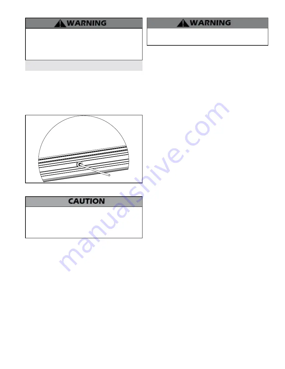
A. Temperature Sensor Insertion
Temperature sensor wells are located on either side of the collector.
Insert the sensor into the well below the hot out port. Ensure that
the sensor and cable used on the collector are high temperature
rated (up to 395
o
F). The sensor cable should not come in direct
contact with the piping.
Ensure that any pipe insulation is watertight. Use silicone sealant to
ensure a watertight seal against the collector.
LP-364-B
01/27/17
Figure 4 - Sensor Cable Detail
B. Header Connection
Never use dielectric unions or galvanized steel fittings when
connecting to a stainless steel storage tank or heater. Use only
copper or brass fittings. Teflon thread sealant must be used on
all connections. Failure to follow this information could result in
premature product failure and property damage. Such damages
ARE NOT covered by product warranty.
Non-Galvanized Connections / Pipe Fitting
To ensure a sound seal, use plumbing thread glue or Teflon tape
approved for use in glycol based systems. Tighten using two
wrenches, taking care not to stress the copper pipe. Do not over
tighten.
Brazing/Sweating/Soldering
to the collector is acceptable, but not
recommended, as doing so can damage the header grommet. Care
must be taken to avoid exposing the silicone rubber seal to the torch
flame. Ideally, place a wet cotton cloth against the rubber seal to
prevent heat damage.
C. Air Purge
Once the inlet and outlet are connected to the plumbing system,
the collector loop should be purged of air.
1. Open Loop
For a system without an auto-air vent, a drain valve on the supply
line should be installed along with a ball valve or a metal coin vent
on the tank side. With the ball valve closed, the drain valve can be
opened to allow air to escape as water pressure forces through the
line.
When opening the drain valve, released water may be hot. Steam
may release as well. Failure to take caution when opening drain valve
could result in serious personal injury or death.
Once the drain valve no longer releases air, close it. Then open the ball
valve so normal operation may begin.
If an auto-air vent is installed on the outlet of the collector, air will
automatically eliminate from the solar line. If using a manual air vent,
open it until all air is eliminated.
2. Pressure Open Loop
Run the pump at the highest speed setting, forcing air out of the
collector and back into the tank. If an auto-air vent is installed on the
outlet of the collector, air will automatically eliminate from the solar
line. If using a manual air vent, open it until all air is eliminated.
3. Closed Loop
The solar loop may be filled with potable water or a glycol / potable
water mix, unpressurized (drain back system), or vented and
pressurized. The exact process will depend on the design of the loop
and components used.
NOTE:
A drain back system does not need to be purged.
D. Plumbing Check
Water vapor may appear on the inside of the collector glass when
initially installed. This is not a problem and will disappear after a few
days of operation. Consult your dealer or factory representative if
water vapor does not clear up after a week of sunny weather.
E. Glycol Freeze Protection
Only use food grade propylene glycol, FDA rated as GRAS (Generally
Recognized As Safe), with additives that provide resistance to
breakdown during high temperatures. Glycol pH should be checked
periodically and replaced as specified by the manufacturer.
F. Insulation
Heavily insulate all piping running to and from the collector with high
quality insulation of at least 0.6” thickness (thicker in cold climates).
Heat loss from the piping can be significant. Particular attention should
be taken to insulate any possible points of heat loss. Insulations should
have a temperature rating of 250
o
F.
Ensure the insulation is tight against the collector casing, thus
minimizing heat loss from the inlet and outlet. High quality silicone
sealant should be used to prevent water from entering the temperature
probe port and/or in between the piping and insulation foam.
Insulation foam exposed to direct sunlight should be protected against
UV related degradation by wrapping/covering with UV protective
material, such as adhesive back aluminum foil, PVC wrap, or similar.
For systems designed to allow stagnation, high temperature rated
insulation such as glass wool or mineral wool should be used on
piping close to the collector (6’). Glass wool insulation may come with
an external foil wrap, but any cuts made during installation should be
sealed with watertight, UV stabilized material, such as adhesive backed
aluminum foil or PVC wrap.
Circulating pump volumes can be a source of significant heat loss and
should be insulated. Some pumps come standard with a molded foam
casing which has good insulation properties. If the pump does not
have any insulation, the same foam insulation used on the pipe can
be used to cover the pump. This insulation should be secured in place
with good quality nylon cable ties or adhesive tape.
NOTE:
Certain pumps are not designed to be insulated. Please contact
the pump manufacturer if in doubt.
All internal and external piping should be insulated. This includes at
least the 3” closest to the hot water outlet of the tank, as this copper
pipe is a significant point of passive heat loss.


