Electrical Connection
Your Invertig 201 AC/DC operates on single-phase 230 volt
power (+/- 20%). The machine is not shipped with a plug. The
input power cord has 3 wires. The yellow-green wire is ground,
and the blue and brown wires are the hot leads.
Input power and will require a 30-amp circuit when operating at
200 amps.
All electrical connections should be performed by a qualified
electrician in accordance with the National Electrical Code and
local codes and ordinances.
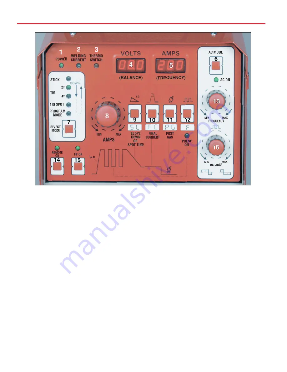
Front Panel Controls
(See Fig. 1)
1. Power Indicator Lamp
This lamp is illuminated when the On-Off switch on the back of
your Invertig 201 is turned to the 1 or “On” position, indicating
the unit is correctly connected to 220 volt AC power.
2. Welding Current Indicator Lamp
When either the foot pedal or the trigger switch on the TIG
torch is depressed, welding current will be applied to the
welding torch and the Welding Current Indicator Lamp will be
illuminated.
If your Invertig 201 AC/DC is in the stick-welding mode, the
welding current indicator lamp will be illuminated all the time.
3. Thermoswitch Indicator Lamp
The thermoswitch indicator lamp will light up when the duty
cycle of your Invertig 201 AC/DC has been exceeded. When
this lamp is illuminated, the machine will no longer weld
because the machine has overheated. Leave the machine
plugged in and turned on so the cooling fans can cool the unit
down. Allow the machine to cool for 15 to 30 minutes, the
thermoswitch should reset automatically and your Invertig will
be ready to weld.
4. Welding Volts - Digital Display
The Welding Volts Digital Display is a multi function display.
When you are welding, this displays the welding voltage.
Pressing other touch pad buttons will display other parameters
in the "VOLTS" display. Those displays will be covered in the
section covering those touch pad buttons.
5. Welding Amps - Digital Display
The Welding Amps Digital Display is a multi function display.
When you are welding, this displays welding amperage.
Pressing other touch pad buttons will display other parameters
in the “APMS” display. Those displays will be covered in the
section covering those touch pad buttons.
(Fig. 1)
4


