


HRW HPD0440BNMR V401 Manual 111116.doc E. & O. E. / Subject to change without notice Page 13 of 43
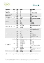
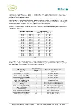
Function Block
Object
Para #
Description
Selection Options
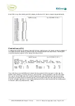
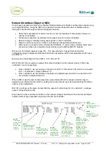
Network Interface
Objects (NIO)
105…112
xxx00=
xxx01=
xxx02=
xxx03=
xxx04=
xxx05=
xxx06=
xxx07=
Target node number
Object Instance type
Target Object Instance within target
node
Sensor type
Read/Write
Read-Value Scaling
Output OR *
Output AND *
Device # in the same network
0 - Disabled
1 - DI
2 - DV
3 - DO
4 - AI
5 - AV
6 - AO
1…65,535
Same as UI selection
0 = Read status of target Instance of
target node
1…112 = Write local Instance status to
target Instance of target node
0 – Normal (apply Sensor Type units
only), 1 - Raw (apply Sensor Type units,
intercept & scaling)
Object #
Object #
* Digital 1 = 1000 (100%) when applied to these analogue logic functions. Analogue values will act as a
Output Minimum when applied to an Output OR and Output Maximum when applied to an Output AND.
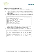
LED 3 & 4 and the audible beeper have a fixed 5sec PWM cycle time with 1sec resolution. Therefore
if digital 1 or 100% is applied then the LED/beeper will be on continuously. If 60% applied then the
LED/beeper will be on for 3sec, off 2sec, on 3sec, and so on. The minimum applied value for an output
reaction is 20% (1sec on, 4sec off). In HPD0460BN these outputs may be driven by peer-to-peer
controllers on the network or via the internal NIO’s reading in object values from other controllers on the
network. HPD0460BNC, T or CT can control objects 25…27 directly using their own internal function
blocks.
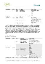
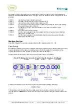
Modbus RTU Gateway
Function Block
Object
Para #
Description
Selection Options
xxx=
Modbus register definition
string;
Device address, register
table #, register row #,
data scaling #, Function
type
Example: 153=1,4,2,0,3
1 is the device address
4 is the data table # (register # / 256)
2 is the data row # (register # - (256*4) -1)
0 is the scaling selection (default 0 = *1)
3 is the data Function type (3 = Holding
Register, Integer)
MRSCxxx=
Apply individual data
scaling after initial
definition string is entered
0=1
1=0.1
2=0.01
3=0.001
4=0.0001
5=0.00001
6=0.000001
7=10
8=100
9=1000
10=10000
11=100000
12=1000000
13=1
14=0.00390625 (1/256)
15=65536
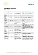
Modbus Register
1…32
153…184
xxx=0…5
Sensor type (Apply units
and local scaling if
required)
Sensor Type as defined in the linearization table.
Units tags and any data manipulation associated
with linearization table rows 12…14 are applied
Modbus Error Count
185
185=
Current Modbus network
comms error count/reset
Read error count / Write 0 to reset


