


HRW HPD0440BNMR V401 Manual 111116.doc E. & O. E. / Subject to change without notice Page 12 of 43
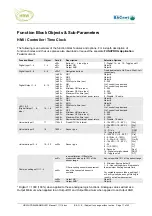
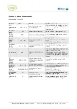
Function Block
Object
Para #
Description
Selection Options
LED 3 & 4
(Analogue Output
1/orange…2/red)
25…26
xx00=
xx01=
xx02=
xx03=
xx04=
OR1
OR2
AND
100%
0%
Object #
Object #
Object #
% of control loop demand
% of control loop demand
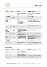
Audible alarm beeper
(Analogue Output 3)
27
xx00=
xx01=
xx02=
xx03=
xx04=
OR1
OR2
AND
100%
0%
Object #
Object #
Object #
% of control loop demand
% of control loop demand
Virtual Digital Input 1…8
29…36
x01=
x02=
Output OR
Output AND
Object #
Object #
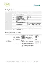
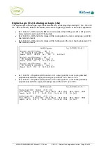
Digital Logic 1…8
37…44
xx00=
xx01=
xx02=
xx03=
xx04=
xx05=
xx06=
xx07=
xx08=
Function
Input1
Input2
Input3
Input4
Delay On
Delay Off
Output OR*
Output AND*
OR, NOR, AND, NAND, XOR, NXOR,
Lead/Lag
Object #
Object #
Object #
Object #
0…65,535 sec
0…65,535 sec
Object #
Object #
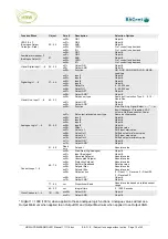
Virtual Univ. Input 1…8
45…52
xx00=
xx01=
xx02=
Set sensor type
Output OR*
Output AND*
Same as UI selection Type 0… 9, 10 -
Hours Run
Object #
Object #
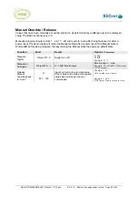
Analogue Logic 1…8
53…60
xx00=
xx01=
xx02=
xx03=
xx04=
xx05=
xx06=
xx07=
xx08=
xx09=
xx10=
xx11=
xx12=
Function
Set output-relevant sensor type
Input1
Input2
Input3
Input4
Offset
Value In 1
Value Out 1
Value In 2
Value Out 2
Output OR *
Output AND *
Max, Min, Avg, Signal-Select, +, -, *, /, or
Eco-Changeover, Proportion, VAV
Volume, Up/Down counter, Power
Same as UI selection
Object #
Object #
Object #
Object #
Relative value
Shift input start value
Shifted output minimum value
Shift input stop value
Shifted output maximum value
Object #
Object #
61…68
Read
only
Setpoint Absolute
value
69…76
xx00=
xx01=
xx02=
xx03=
xx04=
xx05=
xx06=
xx07=
xx08=
xx09=
xx10=
Start/Stop (Dig/Analogue)
Input (Analogue)
Occupied Setpoint
Unoccupied Setpoint
Protection Setpoint
SetPoint Deadband
Setpoint Max.
Setpoint Min.
Output action
Output OR *
Output AND *
Object #
Object #
Absolute value
Absolute value
Absolute value
Relative value
Absolute value
Absolute value
0 – Direct, 1 – Reverse, 2 – Direct 50,
3 – Reverse 50
Object #
Object #
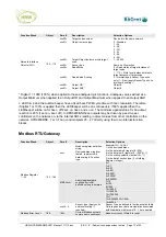
77…84 xx= Proportional
Band
Absolute value based on related sensor
range
Control Loops 1…8
85…92
xx=
Integral time
0…1000 Seconds
Clock Channels 1…4
101…104
xxx00=
xxx01=
Output OR
Output AND
Object #
Object #
* Digital 1 = 1000 (100%) when applied to these analogue logic functions. Analogue values will act as a
Output Minimum when applied to an Output OR and Output Maximum when applied to an Output AND.


