background image


FHD264 

24


© Copyright 2018 Hall Research, Inc.

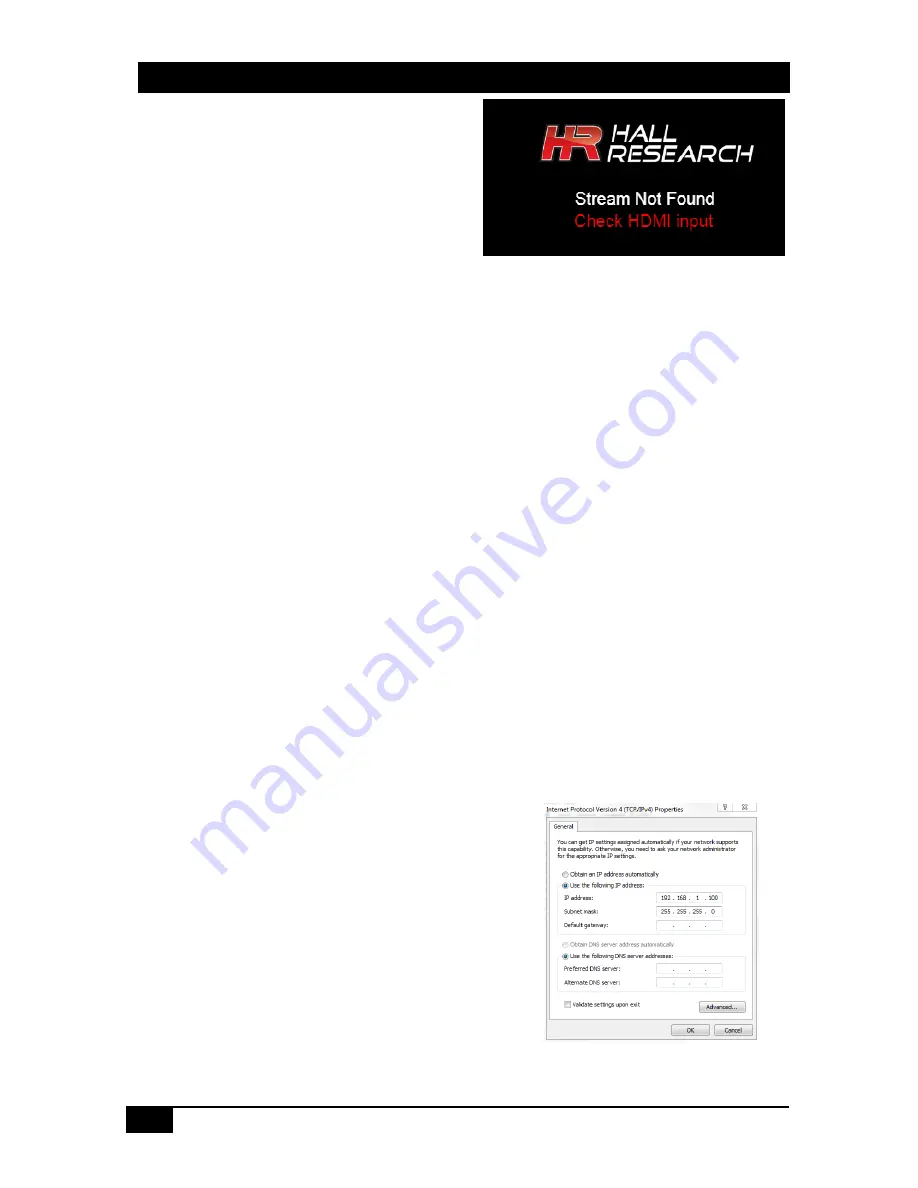
Q1. What is "Stream Not Found"? 

A "Stream Not Found" message is shown on a 
remote display if there is no video source detected 
at the Sender end. This video is generated by the 
Sender in the absence of a source. 


Q2. No picture on the display 


Verify the Cat 5e/6 cables are connected to the FHD264 and the gigabit switch/router 


Verify the display is ON. 


Verify no two Senders are broadcasting in the same group. 


Verify the Receiver is set to the correct Sender group. 


Turn ON the OSD to check whether the Receiver is 

connected

 to the Sender. 


Verify all FHD units and computers in the network have unique IP addresses. 


In a large installation, verify IGMP and JUMBO frames are enabled in your network switch. 
We recommend 

Cisco SG300 Series 

switches. 


Quickly press the RESET button on the unit’s panel to reboot, or power cycle the device. 


If still there is no video, try factory resetting both the Sender and Receiver by holding the 
RESET button on the panel for 10 seconds, or reset from the WebGUI. All settings will be 
erased and set to factory default. 


In a large installation, isolate the Receiver units from the network, and connect them point-to-
point with a Sender to check for possible hardware problems. 


If the video works in a point-to-point configuration, then there is a network problem. Check the 
network and IP configuration of all the units. 


In a one-to-many and many-to-many configuration, if there are displays with different native 
resolutions, then it is highly recommended to use the “Scaler Settings” in the TX’s WebGUI to 
the highest common denominator. 


For example, if a 1080p HDMI source is connected to the Sender and one of the Receivers is 
connected to an HD 720p display, change the settings of the Scaler to “Full HD to HD” in the 
Sender WebGUI so that all the monitors get a resolution of HD 720p video. 


Q3.  How to Change the IP address of the PC? 


In Windows™, it is typically located under Start 

 Control 

Panel 

 Network Sharing center 

 Change adapter 

settings 

 Properties 

 Internet Protocol Version4 

(TCP/IPv4).  

For example, change the IP address field to 192.168.1.100 
(0-255, except 11 or 12) and press "OK" to save the 
configuration.  


Summary of Contents for FHD264-R

Page 1: ...Distribute up to 64 individual HDMI video sources to 250 displays or more Order toll free in the U S 800 959 6439 FREE technical support Call 714 641 6607 or fax 714 641 6698 Mail order Hall Research...

Page 2: ...4 1 1 Changing IP address from Front panel 10 4 2 WebGUI 11 4 3 Telnet Control 12 4 4 Dynamic Virtual Matrix Manager Tool 15 4 5 CNT IP 264 16 5 0 Features 16 5 1 Device ID 16 5 2 Group ID 17 5 3 OSD...

Page 3: ...erference to radio communication It has been designed to comply with the limits for a Class A computing device in accordance with the specifications in Subpart B of Part 15 of FCC rules which are inte...

Page 4: ...ture of the system is its ability to switch Receivers on the fly to show the video of any Sender on the network using Hall Research s DVM Dynamic Virtual Matrix technology Switching is accomplished by...

Page 5: ...dio extraction at both Sender and Receiver end Front Panel with LCD and buttons to display device information and change IP configuration Easy to use WebGUI in each unit accessible from any browser Fr...

Page 6: ...ddress if not using DHCP and Multicast Group channel for each of the Senders see the front panel operation in Section 4 2 Duplicate IP addresses or Groups will cause conflicts Receivers must also all...

Page 7: ...ng IP address from Front panel 6 Repeat the above steps for all the Sender s 7 Make sure each Sender has a unique Group ID Note that two Senders cannot have the same Group ID This will cause conflicts...

Page 8: ...e same at both Sender and Receiver end See Section 4 1 Front Panel Operation for more details 16 Once the Senders and Receivers are configured properly on the network they will be discoverable by Hall...

Page 9: ...DC Plug the supplied 5V DC power supply to the unit if PoE is unavailable HDMI OUT This is a local HDMI loop out for a local display HDMI IN Connect to the HDMI source such as a DVD or Blu ray player...

Page 10: ...and click MENU to apply setting or Hold MENU to discard setting Follow the messages on the LCD for further instructions Figure 6 Front panel operation 4 1 1 Changing IP address from Front panel To ch...

Page 11: ...ork Settings Scaler Settings only for Sender Encoder Settings only for Sender System Settings only for Receiver Fail Safe OSD Debug for troubleshooting Both encoders and decoders can be password prote...

Page 12: ...re case sensitive use lowercase characters as shown Invalid commands result in Unknown Input Command The list CR command displays the list of available commands All Commands are Terminated by CR LF or...

Page 13: ...tings get_hdcp_status On Off Where On Input Video with HDCP Off Input Video without HDCP Query the HDCP status of the video input get_video_lock Lock Unlock Where Lock Stable Input Signal Unlock No in...

Page 14: ...re version factory_reset Processing factory reset System will reboot after few sec Factory reset the device Reboot System will reboot after few sec To reboot the unit get_company_id xxx Query the comp...

Page 15: ...indows Dynamic Virtual Matrix Manager Tool can locate all the FHD264 devices on the network It will list all the devices found by User defined names IP addresses and Multicast Group channels Columns c...

Page 16: ...64 video routing and status Controls External Devices over Serial SoIP Telnet or TCP Create custom control for external devices Real time event scheduling with Real Time clock Compatible with Hall Res...

Page 17: ...Menu Figure 13 OSD Receiver ONLY The FHD264 Receiver shows the following information as an On Screen Display OSD The OSD can be configured as Auto Default ON OFF RX Name This is Receiver s user defin...

Page 18: ...received by all the receivers in the group If a serial device connected to the Receiver transmits data it will be received only by the Sender in the group When receiving data from multiple Receivers t...

Page 19: ...d master_set The registration message format 31 bytes using UDP is as follows TCP Client To send commands to FHD264 TCP port 7000 Maximum command length is 100 bytes TCP Server Listen on port 5050 to...

Page 20: ...the same then Fail Safe will be disabled automatically 5 7 IR FHD264 Supports both IR pass through and IR Control using a single wideband IR detector Any IR signal received in the range of 32 56 KHz a...

Page 21: ...k 5 8 1 Scaler and Encoder Settings If you are using a source with 1080p resolution then use Scale Full HD to option to either transmit the video at the same resolution on the network or to first down...

Page 22: ...s EMX HD AUD Audio Extractor and EDID Manager are recommended for this task 5 10 Firmware Upgrade The firmware upgrade on FHD264 can be completed using the WebGUI Contact Hall Research for more detai...

Page 23: ...Y Fail Safe FS Group ID OSD Disabled 0 Auto Login Username Password Disabled admin admin DHCP IP Subnet Gateway Enabled 192 168 1 11 Sender 192 168 1 12 Receiver 255 255 255 0 192 168 1 1 Baud Rate 11...

Page 24: ...anel for 10 seconds or reset from the WebGUI All settings will be erased and set to factory default In a large installation isolate the Receiver units from the network and connect them point to point...

Page 25: ...e and network congestion Sender Input Ports Output Ports 1 x HDMI 1 x RJ45 1 x HDMI 1 x IR 1 x L R AUDIO 1 x RS 232 Wall Plate Input Ports Output Ports 1 x HDMI 1 x RJ45 1 x IR 1 x L R AUDIO 1 x RS 23...

Page 26: ...FHD264 26 Copyright 2018 Hall Research Inc...

Page 27: ......

Page 28: ...Copyright 2018 Hall Research Inc All rights reserved 1163 Warner Ave Tustin CA 92780 Ph 714 641 6607...

Reviews: