background image

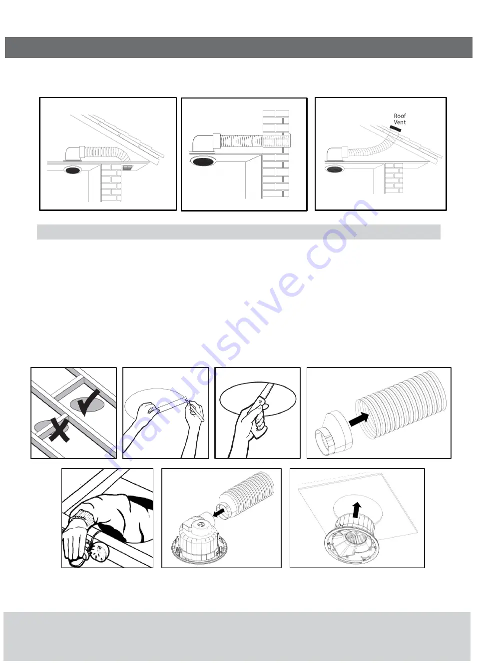
10. The unit can be installed as shown below in fig. A, fig. B and fig. C. When fitted, the duct outlet can be at the same height or lower/higher than the exhaust fan.

11. Vertical ducting with roof vents will result in reduced fan performance, increased noise and condensation/dripping.

Installation (CEILING FAN)

1. Determineposition in ceiling where the exhaust fan is required to be installed (figure 1).

2. Usethe template provided to draw a circle. Todo this, insert a thumb tack at one end and insert a pencil at the other end and scribe a circle (figure 2).

3. Cutout around this line (figure 3).

4. Remove grille from the exhaust fan.

5. Attach duct adaptor to duct with duct tape (figure 4).

6. Ensure that a power outlet is installed in the ceiling near the intended position of the exhaust fan. Ensure that power to the outlet is off. Plug the exhaust fan  into this

outlet (figure 5).

7. Attach duct adaptor to the exhaust fan outlet (figure 6).

8. Insert the unit into the cavity (figure 7).

9. With the unit in place, turn the toggles (4x)clockwise and tighten the screws until the clamps securely grip the ceiling (figure 8).

10. Push grille onto unit and click into position (figure 9).

figure 1

figure 2

figure 3

figure 4

figure 6

figure 7

figure 5

fig.A

fig.B

fig.C

Summary of Contents for EFD01 Series

Page 1: ...t size 160mm EFD01RDWEKIT only ProjectionintoCeiling 190mm ProtrusionfromCeiling 26mm Grille Size Ceiling fan Ø372mm 350 x 350 mm Sound Pressure level at 3m 36 dBA Tested in accordance with AS1217 5 EFD01RDWE EFD01RDMS EFD01RDWEKIT EFD01SQWE EFD01RDWEKIT includes 1 External Grill 2 Ø150mmX 3m Duct 3 Cable ties 4 Duct tape 5 Mounting screws Also available External wall kit accessory R621 6D Please ...

Page 2: ...ted directly above any part of the bath or shower recess or enclosure The unit must be installed within zones 2 and 3 only For further information refer to AS NZS3000 7 Unit Orientation The unit must be installed to ensure the housing outlet and ducting is oriented in parallel to any roofing structures or supports Refer to image below for correct installation orientation Orientation which forces t...

Page 3: ...cilattheother endandscribeacircle figure2 3 Cutoutaroundthisline figure3 4 Removegrille from theexhaust fan 5 Attachductadaptor toductwithduct tape figure4 6 Ensurethatapoweroutlet is installedin the ceiling nearthe intended position ofthe exhaust fan Ensurethatpowerto the outlet isoff Plugtheexhaust fan intothis outlet figure5 7 Attachductadaptor totheexhaust fanoutlet figure6 8 Inserttheunit int...

Page 4: ...e outside hole 2 Remove the inner louvred grille section by gently prying open with a screw driver 3 Attach the vent frame to the ductwith the cable tie firmly 4 Push the vent frame back into the hole and attach with the appropriate screwsfor the wall material 5 Snapin thelouvred grille fromthe outside with thelouvres pointing downwards Note It is desirable to have the ducting as taut as possible ...

Page 5: ... not run backinto thefan housing 11 Precautionsmustbetaken toavoidtheback flow ofgasesinto the roomfrom the openflue ofgasor other fuel burningappliances 12 Thisproducthasbeendesigned for domestic or similar usesandisnot suitable for acommercial installation 13 Thisproductisnotsuitable for installation in hazardous and or corrosiveareas 14 Thematerialin thisproductmayvaryin colourfrom batch tobatc...

Reviews: