HPE FlexFabric 5710 Series Installation Manual Download Page 20


16 

Figure 19 Installing an X722 back-to-front fan tray  


Removing a fan tray 


WARNING! 

  Ensure electricity safety and never touch the rotating fans when you hot-swap a fan tray. 

  To prevent an unbalanced fan from causing loud noise, do not touch the fans, even if they are not 

rotating. 

  Do not touch any bare wires and terminals on a fan tray. 

  Do not place a fan tray in a moist location or let liquid flow into it. 

  Contact Hewlett Packard Enterprise Support if the circuits or components on a fan tray are faulty. 

Do not remove any fan tray components. 


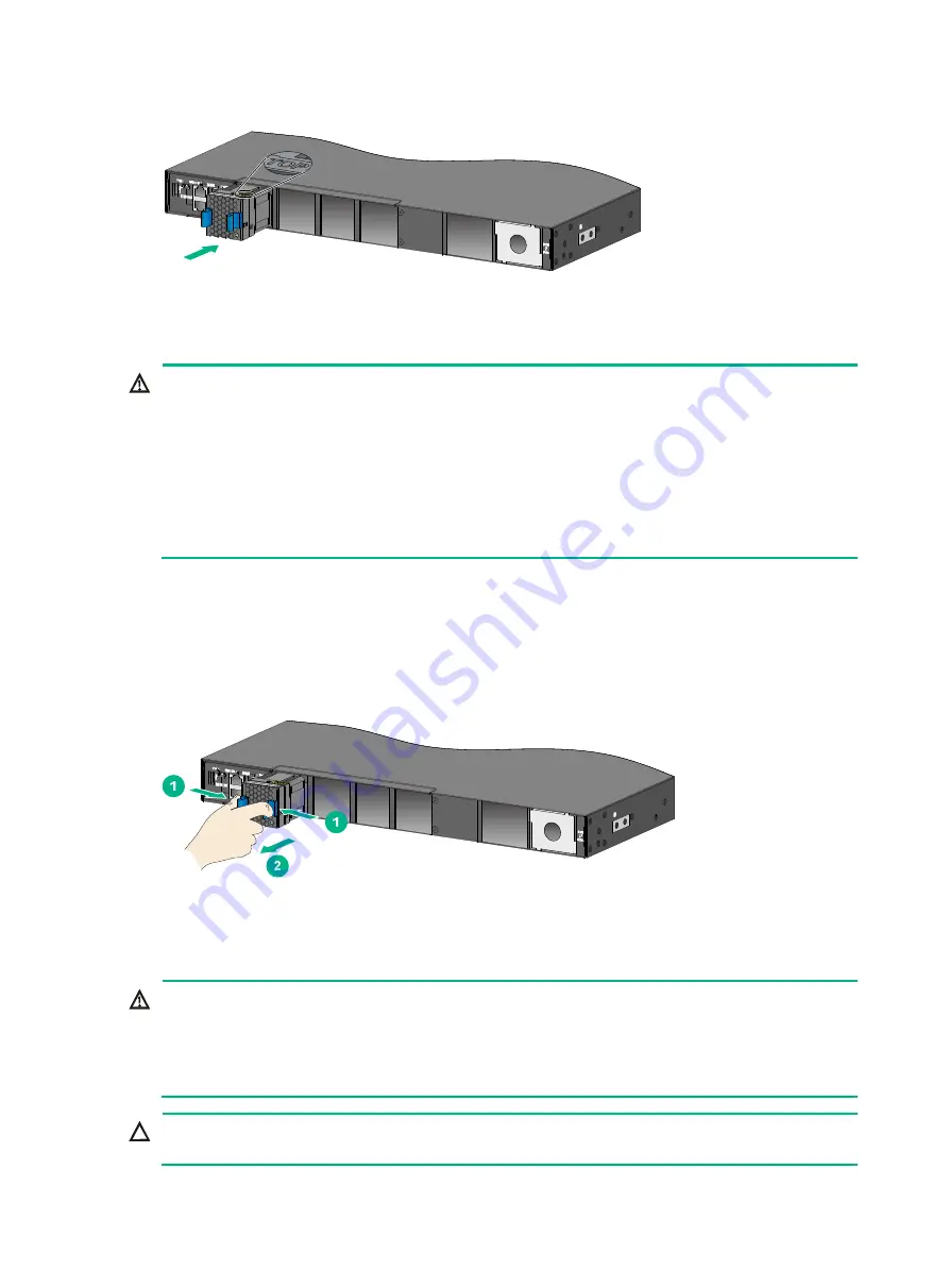
To remove an X721 front-to-back fan tray or X722 back-to-front fan tray: 

1. 

Wear an ESD wrist strap and make sure it makes good skin contact and is reliably grounded. 

2. 

Grasp the fan tray handle and pull out the fan tray slowly along the guide rails. 

3. 

Place the removed fan tray in an antistatic bag. 

Figure 20 Removing an X722 back-to-front fan tray 


Installing and removing a power supply 


WARNING! 

  In power redundancy mode, you can replace a power supply without powering off the switch but 

must strictly follow the installation and procedures in 

Figure 21

 and 

Figure 22

 to avoid any bodily 

injury or damage to the switch. 

  Provide a separate circuit breaker for each power supply. 


CAUTION: 

Do not install power supplies with different models on the same switch. 


Summary of Contents for FlexFabric 5710 Series

Page 1: ...HPE FlexFabric 5710 Switch Series Installation Guide Part number 5200 4984a Document version 6W103 20190403 5200 4984a ...

Page 2: ...tware Computer Software Documentation and Technical Data for Commercial Items are licensed to the U S Government under vendor s standard commercial license Links to third party websites take you outside the Hewlett Packard Enterprise website Hewlett Packard Enterprise has no control over and is not responsible for information outside the Hewlett Packard Enterprise website Acknowledgments Intel Ita...

Page 3: ...ord for a PSR250 12A PSR250 12A1 PSR450 12A PSR450 12A1 power supply 19 Connecting the DC power cord for a PSR450 12D power supply 20 Verifying the installation 20 Accessing the switch for the first time 22 Setting up the configuration environment 22 Connecting the console cable 22 Serial console cable 22 USB mini console cable 23 Connection procedure 23 Setting terminal parameters 25 Powering on ...

Page 4: ...orts 47 Console port 47 Management Ethernet port 47 USB port 48 SFP port 48 QSFP port 50 QSFP28 port 53 1 10GBASE T autosensing Ethernet port 55 LEDs 56 System status LED 56 SFP port LED 56 QSFP port LED 56 QSFP28 port LED 57 Management Ethernet port LEDs 57 1 10GBASE T autosensing Ethernet port LEDs 58 Fan tray alarm LEDs 58 Appendix D Cooling system 59 Document conventions and icons 60 Conventio...

Page 5: ... PSR450 12A JL688A HPE FlexFabric 5710 450W 48V Front to Back DC Power Supply PSR450 12D Fan trays JL594A HPE FlexFabric X721 Front to Back Fan Tray X721 front to back fan tray JL595A HPE FlexFabric X722 Back to Front Fan Tray X722 back to front fan tray For regulatory identification purposes the HPE 5710 switches are assigned Regulatory Model Number RMN The RMNs for these products are listed belo...

Page 6: ...exhausts to the hot aisle Identify the airflow designs of neighboring devices and prevent hot air flowing out of the bottom device from entering the top device The rack is sturdy enough to support the switch and its accessories The rack is reliably grounded To ensure correct operation and long service life of your switch install it in an environment that meets the requirements described in the fol...

Page 7: ...tic wave radiation Common impedance including the grounding system coupling To prevent EMI use the following guidelines If AC power is used use a single phase three wire power receptacle with protection earth PE to filter interference from the power grid Keep the switch far away from radio transmitting stations radar stations and high frequency devices Use electromagnetic shielding for example shi...

Page 8: ...rackets and eight M4 countersunk screws 1 kit HPE 5710 54HT 5380 0091 1 U mounting bracket kit including one pair of mounting brackets and eight M4 countersunk screws 1 kit HPE 5710 30HF 5380 0092 1 U mounting bracket kit including one pair of mounting brackets and eight M4 countersunk screws 1 kit HPE 5710 30HT 5185 8713 1 U long slide rail kit including one pair of slide rails one pair of guide ...

Page 9: ...e 1 All HPE FlexFabric 5710 switches 5185 9579 Grounding screw 2 All HPE FlexFabric 5710 switches 5190 1773 Power supply filler module 1 All HPE FlexFabric 5710 switches 5185 8748 Removable cable tie 1 All power supplies 5185 8627 Console cable 1 All HPE FlexFabric 5710 switches ...

Page 10: ...erprise for permission Otherwise Hewlett Packard Enterprise shall not be liable for any consequence caused thereby Figure 1 Hardware installation flow Start Install the switch Install fan trays Install power supplies Connecet the power cords Verify the installation Power on the switch Operating correctly End Power off the switch Troubleshooting Ground the switch Yes No ...

Page 11: ...igure 3 Figure 2 Mounting brackets Figure 3 1U chassis rail and long slide rail 1 Chassis rail 2 Long slide rail Rack mounting procedures at a glance Figure 4 Rack mounting procedure NOTE If a rack shelf is available you can put the switch on the rack shelf slide the switch to an appropriate location and attach the switch to the rack with the mounting brackets Follow these guidelines when you inst...

Page 12: ...ets chassis rails and long slide rails 621 mm 24 45 in 854 mm 33 62 in Attaching the mounting brackets chassis rails and grounding cable to the chassis The switch has two mounting bracket installation positions on its two sides one near the network port side and one near the power supply side The switch provides a primary grounding point with a grounding sign and an auxiliary grounding point Figur...

Page 13: ...g point 3 Auxiliary grounding point 4 Mounting bracket installation position near the port side Attaching the mounting brackets and chassis rails to the chassis The mounting bracket and chassis rail installation methods are the same for the HPE 5710 54HF and HPE 5710 30HF switches To attach the mounting brackets and chassis rails to the chassis 1 Align the mounting brackets with the screw holes in...

Page 14: ...he screw holes at the front of the side panels see Figure 11 Figure 12 and Figure 13 3 Use M4 screws provided to attach the chassis rails to the chassis Figure 8 Attaching the mounting brackets and chassis rails to an HPE 5710 54HF switch mounting brackets installed near the port side Figure 9 Attaching the mounting brackets and chassis rails to an HPE 5710 54HT switch mounting brackets installed ...

Page 15: ...ct grounding points as required The primary grounding point and auxiliary grounding point are located on the left side panel If you use one of these grounding points you must connect the grounding cable to the grounding point before you mount the switch in the rack This section uses the primary grounding point on the HPE 5710 54HF switch as an example To connect the grounding cable to a grounding ...

Page 16: ...es the 1U long slide rails as an example To attach the slide rails to the rack 1 Identify the rack attachment position for the slide rails 2 Install floating nuts user supplied in the mounting holes in the rack posts 3 Align the screw holes in one slide rail with the floating nuts in the rack post on one side and use screws user supplied to attach the slide rail to the rack as shown in Figure 15 4...

Page 17: ...at the same level as the slide rails 5 One person performs the following operations a Supporting the bottom of the switch aligns the chassis rails with the slide rails on the rack posts b Pushes the switch slowly to slide the chassis rails along the slide rails until the mounting brackets are flush with the rack posts 6 The other person uses screws user supplied to attach the mounting brackets to ...

Page 18: ...entral ground is directly connected to the chassis to form the chassis ground commonly known as PGND You must securely connect this chassis ground to the earth so the faradism and leakage electricity can be safely released to the earth to minimize EMI susceptibility of the switch To ground the switch by using a grounding strip 1 Attach the two hole grounding lug at one end of the grounding cable t...

Page 19: ...tray or the connectors on the backplane insert the fan tray gently If you encounter a hard resistance while inserting the fan tray pull out the fan tray and insert it again Select appropriate fan trays as needed For the optional fan trays and their specifications see Fan trays To installing an X721 front to back fan tray or X722 back to front fan tray 1 Wear an ESD wrist strap and make sure it mak...

Page 20: ...move an X721 front to back fan tray or X722 back to front fan tray 1 Wear an ESD wrist strap and make sure it makes good skin contact and is reliably grounded 2 Grasp the fan tray handle and pull out the fan tray slowly along the guide rails 3 Place the removed fan tray in an antistatic bag Figure 20 Removing an X722 back to front fan tray Installing and removing a power supply WARNING In power re...

Page 21: ...r module slot is installed with a filler panel The installation procedure is the same for power supplies of different models The following procedure installs a PSR250 12A power supply on an HPE 5710 54HF switch To install a power supply 1 Wear an ESD wrist strap and make sure it makes good skin contact and is reliably grounded 2 Remove the filler module from the target power supply slot if any as ...

Page 22: ...move the power cord 3 Hold the handle on the power supply with one hand pivot the latch on the power supply to the right with your thumb and pull the power supply part way out of the slot as shown in Figure 25 4 Supporting the power supply bottom with one hand slowly pull the power supply out with the other hand 5 Put away the removed power supply in an antistatic bag for future use Figure 25 Remo...

Page 23: ...e a flat head screwdriver to loosen the screws on the DC power cord connector 2 Pull the DC power cord connector out Connecting the power cord WARNING Provide a circuit breaker for each power input When you connect a power cord make sure the circuit breaker is switched off Connecting the power cord for a PSR250 12A PSR250 12A1 PSR450 12A PSR450 12A1 power supply 1 Insert the power cord connector s...

Page 24: ...r to fasten the screws on the power cord connector as shown in Figure 28 3 Use a cable tie to secure the power cord to the handle of the power supply 4 Connect the other end of the power cord to the DC power source Figure 28 Connecting the DC power cord for a PSR450 12D power supply 1 Insert the power cord connector into the DC input power receptacle of the power supply 2 Use a flat head screwdriv...

Page 25: ...re correctly connected If part of the network cable for a port is routed outdoors verify that a network port lightning protector is used for the port If a power line is routed from outdoors verify that a surge protected power strip is used for the switch ...

Page 26: ... use the two ways together on the same HPE 5710 switch The example uses a console cable to connect a console terminal PC to the serial console port on the switch Figure 29 Connecting the serial console port to a terminal Connecting the console cable Serial console cable A serial console cable is an 8 core cable with a crimped RJ 45 connector at one end for connecting to the serial console port of ...

Page 27: ...port The serial ports on PCs do not support hot swapping If the switch has been powered on connect the serial console cable to the PC before connecting to the switch and when you disconnect the cable first disconnect from the switch To connect to the configuration terminal through the USB mini console cable 1 Connect the standard USB Type A connector to the USB port of the configuration terminal 2...

Page 28: ...24 Figure 31 Device Driver Installation Wizard 6 Click Continue Anyway if the following dialog box appears Figure 32 Software Installation ...

Page 29: ...t the terminal emulator programs see the user guides for these programs The following are the required terminal settings Bits per second 9600 Data bits 8 Stop bits 1 Parity None Flow control None Powering on the switch Before powering on the switch verify that the following conditions are met The power cord is correctly connected The input power voltage meets the requirement of the switch The cons...

Page 30: ...iffer with software versions For more information about Boot ROM menu options see the software matching release notes for the device After the startup completes you can access the CLI to configure the switch For more information about the configuration commands and CLI see HPE FlexFabric 5710 Switch Series Configuration Guides and HPE FlexFabric 5710 Switch Series Command References ...

Page 31: ...witch called an IRF fabric for flattened network topology and high availability scalability and manageability The switch can set up an IRF fabric only with switches from the same switch series To set up IRF links between two switches use the 10 GE 40 GE or 100 GE ports IRF fabric setup flowchart Figure 34 IRF fabric setup flowchart ...

Page 32: ...switches except the master switch automatically reboot and the IRF fabric is established Planning IRF fabric setup This section describes issues that an IRF fabric setup plan must cover Planning IRF fabric size and the installation site Choose switch models and identify the number of required IRF member switches depending on the user density and upstream bandwidth requirements The switching capaci...

Page 33: ...chain topology or more reliably ring topology In ring topology the failure of one IRF link does not cause the IRF fabric to split as in daisy chain topology Rather the IRF fabric changes to a daisy chain topology without interrupting network services You connect the IRF member switches through IRF ports the logical interfaces for the connections between IRF member switches Each IRF member switch h...

Page 34: ... ports to be used for IRF connections on the member switches according to your topology and connection scheme All the 10GBase T Ethernet ports SFP ports QSFP ports and QSFP28 ports on the HPE FlexFabric 5710 switch can be used for IRF connections Planning the cabling scheme You can use twisted pair cables SFP QSFP QSFP28 cables or SFP QSFP QSFP28 transceiver modules and optical fibers to connect t...

Page 35: ...optical fibers The switches in the ring topology see Figure 38 are in the same order as connected in the rack Figure 37 Connecting the switches in one rack Figure 38 IRF fabric topology Connecting the IRF member switches in a ToR solution You can install IRF member switches in different racks side by side to deploy a top of rack ToR solution Figure 39 shows an example for connecting four top of ra...

Page 36: ...logies Configuration Guide depending on the software version Connecting the physical IRF ports CAUTION Wear an ESD wrist strap when you connect cables or transceiver modules and optical fibers For more information see the installation guide for the transceiver modules Use cables or transceiver modules and optical fibers to connect the IRF member switches as planned Accessing the IRF fabric to veri...

Page 37: ...ormation display irf topology NOTE To avoid IP address collision and network problems configure at least one multi active detection MAD mechanism to detect the presence of multiple identical IRF fabrics and handle collisions For more information about MAD detection see HPE FlexFabric 5710 Switch Series IRF Configuration Guide or HPE FlexFabric 5710 Switch Series Virtual Technologies Configuration ...

Page 38: ...ood ventilation is provided for the power supply 4 If the issue persists contact the Hewlett Packard Enterprise Support To replace a power supply see Installing and removing a power supply Fan tray failure CAUTION If more than one fan tray fails during the switch operation do not remove the failed fan trays simultaneously Replace the fan trays one by one and finish replacing each fan tray within 3...

Page 39: ...he following settings are configured for the terminal Baud rate 9600 Data bits 8 Stop bits 1 Parity None Flow control None 4 If the issue persists contact Hewlett Packard Enterprise Support Garbled display on the configuration terminal Symptom The configuration terminal displays garbled text Solution To resolve the issue 1 Verify that the following settings are configured for the terminal Baud rat...

Page 40: ...an tray 1 5 Fan tray 2 6 Fan tray 3 7 Fan tray 4 8 Power supply 1 9 Power supply 2 10 Fiber management Ethernet port 11 Copper management Ethernet port 12 Console port 13 Mini USB console port 14 USB port An HPE 5710 54HF switch comes with power supply slot PWR1 empty and power supply slot PWR2 installed with a filler module In Figure 41 two PSR250 12A power supplies are installed in the power sup...

Page 41: ... the fan tray slots For more information about installing and removing a fan tray see Installing and removing a fan tray Figure 42 Left side panel 1 Primary grounding point 2 Auxiliary grounding point HPE 5710 54HT Figure 43 Front panel 1 1 10GBase T autosensing Ethernet port 2 1 10GBase T autosensing Ethernet port LED 3 QSFP port 4 QSFP28 port 5 QSFP28 port LED 6 QSFP port LED 1 2 2 1 3 4 6 5 ...

Page 42: ...and power supply slot PWR2 installed with a filler module In Figure 44 two PSR450 12A1 power supplies are installed in the power supply slots For more information about installing and removing a power supply see Installing and removing a power supply An HPE 5710 54HT switch comes with the five fan tray slots empty You must install five fan trays of the same model for the switch In Figure 44 five X...

Page 43: ...t 14 USB port An HPE 5710 30HF switch comes with power supply slot PWR1 empty and power supply slot PWR2 installed with a filler module In Figure 41 two PSR250 12A power supplies are installed in the power supply slots For more information about installing and removing a power supply see Installing and removing a power supply An HPE 5710 30HF switch comes with the four fan tray slots empty You mus...

Page 44: ...QSFP28 port 5 QSFP28 port LED 6 QSFP port LED Figure 50 Rear panel 1 Fiber management Ethernet port 2 Copper management Ethernet port 3 Console port 4 Mini USB console port 5 Fan tray 1 6 Fan tray 2 7 Fan tray 3 8 Fan tray 4 9 Power supply 1 10 Power supply 2 11 USB port 12 System status LED SYS 13 LINK ACT LED for the copper management Ethernet port 14 LINK ACT LED for the fiber management Ethern...

Page 45: ...rimary grounding point 2 Auxiliary grounding point Technical specifications Table 9 Technical specifications 1 Item HPE 5710 54HF HPE 5710 30HF Dimensions H W D 44 440 400 mm 1 73 17 32 15 75 in 44 440 400 mm 1 73 17 32 15 75 in Weight 10 kg 22 05 lb 10 kg 22 05 lb Console ports 1 mini USB console port 1 serial console port 1 mini USB console port 1 serial console port Management Ethernet ports 1 ...

Page 46: ...12A PSR450 12A1 Single AC input 130 W Dual AC inputs 138 W PSR450 12D Single DC input 133 W Dual DC inputs 140 W Chassis leakage current compliance UL60950 1 EN60950 1 IEC60950 1 GB4943 Melting current of power supply fuse PSR250 12A PSR250 12A1 6 3 A 250 VAC PSR450 12A PSR450 12A1 10 A 250 VAC PSR450 12D 20 A 125 VDC Operating temperature 0 C to 45 C 32 F to 113 F Operating humidity 10 RH to 90 R...

Page 47: ... PSR450 12D Single DC input 97 W Dual DC inputs 104 W PSR250 12A PSR250 12A1 Single AC input 77 W Dual AC inputs 83 W PSR450 12A PSR450 12A1 Single AC input 78 W Dual AC inputs 87 W PSR450 12D Single DC input 78 W Dual DC inputs 85 W Maximum power consumption PSR450 12A PSR450 12A1 Single AC input 255 W Dual AC inputs 258 W PSR450 12D Single DC input 259 W Dual DC inputs 264 W PSR250 12A PSR250 12...

Page 48: ...44 Item HPE 5710 54HT HPE 5710 30HT Operating temperature 0 C to 45 C 32 F to 113 F Operating humidity 10 RH to 90 RH noncondensing Fire resistance compliance UL60950 1 EN60950 1 IEC60950 1 GB4943 ...

Page 49: ...250 12A Yes Yes No Yes PSR250 12A1 Yes Yes No Yes PSR450 12A Yes Yes Yes Yes PSR450 12A1 Yes Yes Yes Yes PSR450 12D Yes Yes Yes Yes Fan trays X721 front to back fan tray Yes Yes Yes Yes X722 back to front fan tray Yes Yes Yes Yes CAUTION For adequate heat dissipation install a fan tray in each fan tray slot and make sure the fan trays are the same model As a best practice install power supplies of...

Page 50: ...50 W For more information about the power supplies see HPE PSR450 Power Supply Series User Guide PSR450 12D with an airflow direction from the port side to the power supply side Rated input voltage 48 to 60 VDC Max input voltage 36 to 72 VDC Max output power 450 W Fan trays Table 13 Fan tray specifications Item Specifications X722 back to front fan tray Fans One 40 40 28 mm 1 57 1 57 1 10 in fan F...

Page 51: ...l emulation program Management Ethernet port The switch provides a copper and a fiber management Ethernet port You can connect this port to a PC or management station for loading and debugging software or remote management Table 15 Copper management Ethernet port specifications Item Specification Connector type RJ 45 Connector quantity 1 Port transmission rate 10 100 1000 Mbps half full duplex Tra...

Page 52: ...rprise does not guarantee the correct operation of all USB devices on the switch If a USB device fails to operate on the switch replace it with one from another manufacturer SFP port The HPE 5710 54HF and HPE 5710 30HF switches provide SFP ports You can install Gigabit SFP transceiver modules in Table 18 10 Gigabit SFP transceiver modules in Table 19 and 10 Gigabit SFP cables in Table 20 in the SF...

Page 53: ...9 10 Gigabit SFP transceiver modules available for the SFP ports Product code HPE description Central wavelength nm Connec tor Fiber type and diameter µm Modal bandwidth MHz km Max transmission distance JD092B HPE X130 10G SFP LC SR Transceiver 850 LC Multi mode 50 125 2000 300 m 984 25 ft 500 82 m 269 03 ft 400 66 m 216 54 ft Multi mode 62 5 125 200 33 m 108 27 ft 160 26 m 85 30 ft JD094B HPE X13...

Page 54: ...s SFP transceiver modules or SFP cables for the SFP ports on the switch The HPE SFP transceiver modules SFP transceiver modules and SFP cables are subject to change over time For the most up to date list of SFP transceiver modules SFP transceiver modules and SFP cables contact Hewlett Packard Enterprise Support or marketing staff For more information about HPE SFP transceiver modules SFP transceiv...

Page 55: ...1331 LC Single mode 9 125 N A 10 km 6 21 miles JL286A HPE X140 40G QSFP LC LR4L 2km SM Transceiver Four lanes 1271 1291 1311 1331 LC Single mode 9 125 N A 2 km 1 24 miles Table 23 40G QSFP cables available for the QSFP ports Product Code HPE description Cable length JG326A HPE X240 40G QSFP QSFP 1m Direct Attach Copper Cable 1 m 3 28 ft JG327A HPE X240 40G QSFP QSFP 3m Direct Attach Copper Cable 3...

Page 56: ...P 7m Active Optical Cable 7 m 22 97 ft 40 Gbps JL288A HPE X2A0 40G QSFP to QSFP 10m Active Optical Cable 10 m 32 81 ft JL289A HPE X2A0 40G QSFP to QSFP 20m Active Optical Cable 20 m 65 62 ft Figure 54 QSFP cable 1 Connector 2 Pull latch Figure 55 40G QSFP to 4 x SFP cable 1 QSFP module 2 QSFP side pull latch 3 SFP side pull latch 4 SFP module ...

Page 57: ...port or marketing staff For more information about HPE QSFP transceiver modules QSFP cables and 40G QSFP to 4 SFP cables see HPE Transceiver Modules User Guide QSFP28 port The switch provides QSFP28 ports The QSFP28 ports are 40GE ports by default To change the ports to 100GE ports execute the related command from the CLI For more information see Ethernet interface commands in HPE FlexFabric 5710 ...

Page 58: ... X150 100G QSFP28 CWDM4 2km SM Transceiver Four lanes 1264 5 to 1277 5 1284 5 to 1297 5 1304 5 to 1317 5 1324 5 to 1337 5 LC Single mod e 9 125 N A 2 km 1 24 miles Table 27 QSFP28 cables available for the QSFP28 ports Product Code HPE description Cable length JL271A HPE X240 100G QSFP28 to QSFP28 1m Direct Attach Copper Cable 1 m 3 28 ft JL272A HPE X240 100G QSFP28 to QSFP28 3m Direct Attach Coppe...

Page 59: ...rovides 1 10GBASE T autosensing Ethernet ports Table 29 1 10GBASE T autosensing Ethernet port specifications Item Specification Connector type RJ 45 Port transmission rate 1 10 Gbps full duplex MDI MDI X autosensing Transmission medium and max transmission distance 55 m 180 45 ft over category 6 unshielded twisted pair cable 100 m 328 08 ft over category 6 shielded twisted pair cable 100 m 328 08 ...

Page 60: ...reen The switch is operating correctly Flashing green The switch is performing power on self test POST Steady red The system has failed POST or a fault has occurred Flashing red Some ports have failed POST Off The switch is powered off or has failed to start up SFP port LED Each SFP port has a status LED to show its operating status and activities Table 31 SFP port LED description LED status Descr...

Page 61: ...eiving data at 100 Gbps Steady yellow A transceiver module or cable has been correctly installed The port has a link and is operating at 10 40 Gbps Flashing yellow 3 Hz The port is sending or receiving data at 10 40 Gbps Off No transceiver module or cable has been installed or no link is present on the port Management Ethernet port LEDs The switch provides a LINK ACT LED for each management Ethern...

Page 62: ...ing or receiving data at 10 Gbps Steady yellow The port has a link and is operating at 1 Gbps Flashing yellow The port is sending or receiving data at 1 Gbps Off No link is present on the port Fan tray alarm LEDs The X721 front to back fan tray and X722 back to front fan tray provide an Alarm LED Table 37 Fan tray alarm LED description Status Description On The fan tray is faulty Off The fan tray ...

Page 63: ...ion site for the switch Table 38 Cooling system for the switch Available fan trays Airflow direction X722 back to front fan tray From the power supply side to the port side X721 front to back fan tray From the port side to the power supply side Figure 59 Airflow from the power supply side to the port side through the HPE 5710 54HF chassis with X722 back to front fan tray Figure 60 Airflow from the...

Page 64: ...ntax choices separated by vertical bars from which you select one choice multiple choices or none 1 n The argument or keyword and argument combination before the ampersand sign can be entered 1 to n times A line that starts with a pound sign is comments GUI conventions Convention Description Boldface Window names button names field names and menu items are in Boldface For example the New User wind...

Page 65: ...epresents a wireless terminator unit Represents a wireless terminator Represents a mesh access point Represents omnidirectional signals Represents directional signals Represents a security product such as a firewall UTM multiservice security gateway or load balancing device Represents a security module such as a firewall load balancing NetStream SSL VPN IPS or ACG module Examples provided in this ...

Page 66: ...s provide a mechanism for accessing software updates through the product interface Review your product documentation to identify the recommended software update method To download product updates go to either of the following Hewlett Packard Enterprise Support Center Get connected with updates page www hpe com support e updates Software Depot website www hpe com support softwaredepot To view and u...

Page 67: ...ht Remote Support not applicable to all devices www hpe com info insightremotesupport docs Customer self repair Hewlett Packard Enterprise customer self repair CSR programs allow you to repair your product If a CSR part needs to be replaced it will be shipped directly to you so that you can install it at your convenience Some parts do not qualify for CSR Your Hewlett Packard Enterprise authorized ...

Page 68: ...d any errors suggestions or comments to Documentation Feedback docsfeedback hpe com When submitting your feedback include the document title part number edition and publication date located on the front cover of the document For online help content include the product name product version help edition and publication date located on the legal notices page ...

Page 69: ... Fan tray failure 34 Fan trays 46 G Grounding the switch by using a grounding strip 14 I Installation accessories 4 Installation tools 3 Installing and removing a fan tray 15 Installing and removing a power supply 16 Installing the switch in a 19 inch rack 7 IRF fabric setup flowchart 27 L LEDs 56 N Network topology icons 61 P Planning IRF fabric setup 28 Ports 47 Power supplies 45 Power supply fa...

Reviews: