background image

58  

Operator's manual 

M 824 

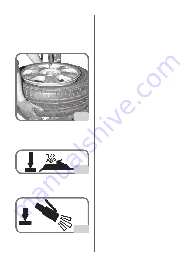
- Connect the Doyfe inflator chuck on the air 

hose to the valve stem (Fig. 28).

- Hold the tyre with your hands and lift it until 

there is a slight gap between the lower bead 

and bottom edge of the rim in order to close 

the upper bead and the top of the rim (Fig. 

28).

28

- Fully press the inflation pedal down for a 

short period to the bead seating position (fig. 

29a). The tyre will expand and the beads will 

seat.

29a

- Continue to press the pedal in the inflation 

position (fig. 29b) until the beads are com-

pletely inserted.

29b

Note

: to improve the operation of the tubeless 

tyre inflation system the compressed air line 

pressure must be between 8/10 bar.

TROUBLESHOOTING

Turntable does not turn

Power cord conductor shorting to 

ground.

  Check the wiring.

Motor shorted.

  Replace the fuses

➥ 

Replace the motor.

Rotation control pedal fails to 

return to the central position

Control spring broken.

➥ 

Replace the command spring.

Bead breaker pedal and table 

top pedal do not return to home 

position

Control spring broken.

➥ 

Replace the pedal return spring.

No oil in lubricator.

  Top up lubricator with SAE20 non-

detergent oil.

Air leak inside the machine

Air leak from bead breaker cock.

➥ 

Replace the cock.

➥ 

Replace the bead breaker cylinder.

Air leak from the table top cock.

➥ 

Replace the turntable cylinder.

➥ 

Replace the swivel connector.

Bead breaker cylinder lacks 

force, fails to break beads and 

leaks air

Silencer plugged.

➥ 

Replace the silencer.

Cylinder seals worn.

➥ 

Replace the gaskets.

➥ 

Replace the bead breaker cylinder.

Summary of Contents for M 824

Page 1: ...an ais Utilisation et entretien Deutsch Betriebs und Wartungsanleitung Espa ol Uso y mantenimiento Cod 4 120285A delL 11 2017 SMONTAGOMME TYRE CHANGER DESMONTADOR DE NEUM TICOS REIFENMONTIERMASCHINE D...

Page 2: ...INTENDED OPERATING CONDITIONS 47 MAIN WORKING ELEMENTS OF THE MACHINE 48 Danger warning decals 50 BEAD BREAKING 50 Deciding from which side of the wheel the tyre must be demounted 50 Special instructi...

Page 3: ...d Kg 278 FS version in cardboard 282 Kg in wood 292 Kg INTRODUCTION The purpose of this manual is to provide the owner and machine operator with ef fective safe instructions for the operation and main...

Page 4: ...ater date if necessary UNPACKING ASSEMBLY WARNING Take the utmost care when unpacking assembling hoisting and installing the machine as described below Failure to observe these instructions can damage...

Page 5: ...asten the tank 4 to the machine with nuts and washers R and tighten the clamp O onto the hose Q FS version only Assemble the different parts of the machine Fig 2 Remove the side cover Insert the air p...

Page 6: ...ty at work must be complied with when choosing the installation position IMPORTANT for the correct and safe operation of the machine the lighting level in the place of use should be at least 300 lux W...

Page 7: ...al electrical layout diagram included in this manual ensure that the workshop electrical system includes a functional grounding circuit prevent unauthorised use of the ma chine always disconnect the p...

Page 8: ...e area of operations Make sure that the machine has been installed in compliance with established legislation and standards Make sure that all machine operators are suitable trained that they are capa...

Page 9: ...and demounting tyres All func tions are controlled by the operator via ped als and hand operated valves and levers TECHNICAL DATA Turntable clamping capacity internal clamping from 13 external clampin...

Page 10: ...ipped as described in this manual WARNING Any use other than those described in this manual is to be considered impro per and unreasonable The machine is equipped with an inflation system independent...

Page 11: ...ver A and turn handle B to lock the vertical arm Turn handle B only to release the verti cal arm 3 Vertical and horizontal arm to position the mounting demounting tool 4 Mounting demounting tool for m...

Page 12: ...gu lates pressure filters removes humidity of and lubricates the compressed air supply 19 Lube bottle 20 Inflation nozzles air introduced through these nozzles pushes the beads out ward to form a seal...

Page 13: ...REAKING WARNING During this operation noise levels assessed at 85 dB A may occur The refore we advise operators to wear hearing protection devices Deciding from which side of the wheel the tyre must b...

Page 14: ...ndence with the valve hole and on the lower and upper side of the wheel Fig 9b A B C 9b A Valve hole B Slight curvature C Pronounced curvature Wheels for Corvette BMW Lam borghini and other wheels wit...

Page 15: ...necessary to break the bead at several points to free it completely After detaching the beads remove the old balancing weights Thoroughly lubricate the sides of the tyre around the entire circumferen...

Page 16: ...Operator s manual M 824 53 EN 10 20 13 23 14 24 min 17 14...

Page 17: ...e rim edge fig 16 IMPORTANT pressing the button locks both the vertical and horizontal arms simultaneously This space between the rim and the verti cal slide will be maintained for as long as the butt...

Page 18: ...s or wheels with easily damaged paint we recommend fitting the spe cific plastic protectors on the lever WARNING Grip the bead lifting tool firmly during use Lift the top bead over the front of the de...

Page 19: ...EDURE For a detailed description of the UHP and RUN FLAT tyre mounting demounting procedure please refer to the instruc tions in the manual prepared by WDK German Tyre Industry Association INFLATION W...

Page 20: ...R exceed the pressure value re commended by the tyre manufacturer Tyres may explode if inflated beyond these limits or their structure may be damaged seriously although not visibly at that moment KEEP...

Page 21: ...een 8 10 bar TROUBLESHOOTING Turntable does not turn Power cord conductor shorting to ground Check the wiring Motor shorted Replace the fuses Replace the motor Rotation control pedal fails to return t...

Page 22: ...30 Vertical head lifts too little or too far from rim Clamping plate not adjusted Adjust the plate Vertical slide ascends under strain Defective clamping plate Replace the plate Clamping plate not ad...

Page 23: ...ts are suitably immobilised WARNING Do not remove or alter any part of this machine only technical assistance personnel is permitted to do so DANGER When the machine is disconnected from the air suppl...

Page 24: ...o avoid building up and raising dust as far as possible condensation drain system therefore in conditions of normal use special main tenance is not required The condensate may however be drained manua...

Page 25: ...be hazardous to the environment or to human health Furthermore this helps to recover recycle and reuse many of the materials contained in these products Electrical and electronic manufacturers and di...

Page 26: ...rivers or streams Contact a specialised firm for disposal Oil spreading or leakage When the oil has been removed de grease the area with suitable solvents taking care to disperse solvent fumes Dispose...

Page 27: ...Relief valve 22 5 2 NO Valve 23 Tool actuator cylinder 32 Inflation limiter unit GLOSSARY Tubeless tyre inflation system Inflation system that makes easier the infla tion of tubeless tyres Insertion...

Page 28: ...Operator s manual M 824 65 EN 32...

Page 29: ...66 Operator s manual M 824 33...

Page 30: ...Operator s manual M 824 67 EN 34...

Page 31: ...68 Operator s manual M 824 35...

Page 32: ...Operator s manual M 824 69 EN STANDARD VERSION...

Page 33: ...70 Operator s manual M 824 FS VERSION...

Page 34: ...Operator s manual M 824 71 EN STANDARD VERSION AIR MOTOR...

Page 35: ...72 Operator s manual M 824 FS VERSION AIR MOTOR...

Page 36: ...Operator s manual M 824 73 EN Notes...

Page 37: ...74 Operator s manual M 824 Notes...

Reviews:

Related manuals for M 824