HP Tc2110 - Server - 128 MB RAM Maintenance Manual Download Page 101

Chapter 7 

Replacing Parts 


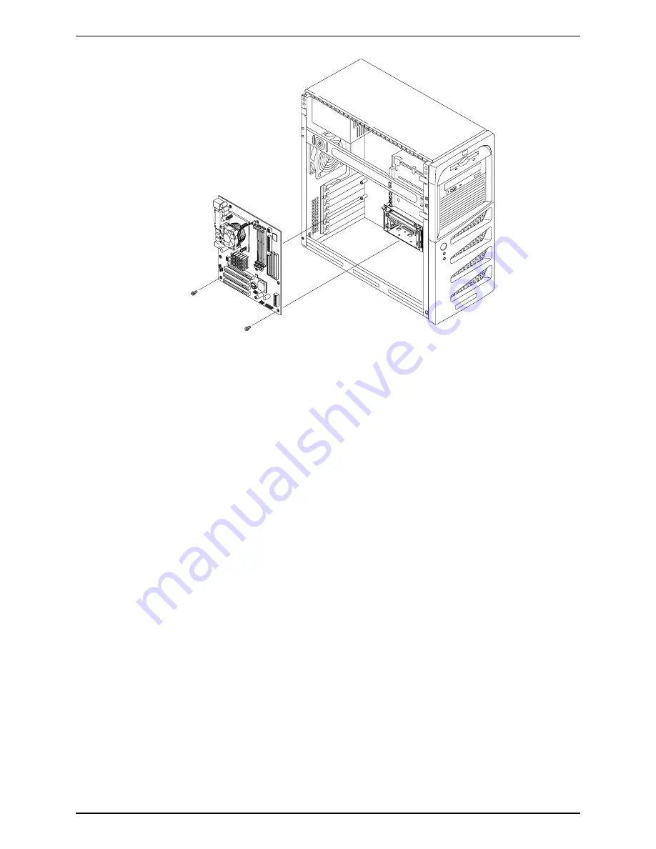
Figure 7-20. Removing and Replacing the System Board 

Replacing the System Board 

1.  Remove the replacement system board and any cables from the anti-static shipping container. 

2.  Place the system board on an anti-static pad and set all jumper connections as recorded during the 

system board removal.  

3.  Insert the new system board, lining up the rear connectors carefully. 

4.  Install all the screws into the system board to secure it to the chassis. 

5.  Replace all cables that were disconnected during the previous removal. 

6.  Replace the DIMMs, processor and heat sink-cooling fan and accessory boards.  

7.  Replace the external cover on the rear panel. Place the cover over the ports and press to snap it in place. 

8.  Replace the left side cover. 

9.  Return the Server to the upright position. 

10.  Connect the power cord and any external cables to the Server.  

11.  Power on the Server as described in Chapter 1, “Controls and Indicators.” 

12.  Enter the (BIOS) Setup Utility and set the BIOS configuration. 

13.  Reboot the Server and verify the Server is operating correctly. 


95 

Summary of Contents for Tc2110 - Server - 128 MB RAM

Page 1: ...HP Server tc2110 Operations and Maintenance Guide Online Version 1 10 December 2002 ...

Page 2: ...ed reproduced or translated to another language without the prior written consent of Hewlett Packard Company Windows NT and Windows 2000 are registered trademarks of Microsoft in the U S and other countries Novell and NetWare are registered trademarks of Novell Inc Torx is a registered trademark of CamCar Textron Inc Hewlett Packard Company Network Server Division Technical Communications MS 45SLE...

Page 3: ...he HP Server 15 Removing the Left Side Cover 15 Replacing the Left Side Cover 16 Removing the Upper Bezel 17 Replacing the Upper Bezel 18 Mass Storage 19 Mass Storage Guidelines 20 Boot Priority 21 IDE Mass Storage Devices 21 SCSI Mass Storage Devices 22 Installing a Second Hard Disk Drive Drive Cage Mounted 23 Installing a Third Hard Disk Drive Tray Mounted 25 Installing an Optional CD ROM or DVD...

Page 4: ...lities 53 About Error Messages 54 Advantages and Limitations of Hardware Diagnostics 54 HP Toptools 54 5 Error Messages 55 Power On Self Test POST Error Messages 55 Beep Codes 55 6 Troubleshooting Error Bookmark not defined Preventive Maintenance Procedures Error Bookmark not defined Troubleshooting Checklist Error Bookmark not defined Server Does Not Power On Error Bookmark not defined Server Pow...

Page 5: ...ss Storage Devices 74 Removing the Flexible Disk Drive 74 Replacing the Flexible Disk Drive 75 Removing the CD ROM 75 Replacing the CD ROM 76 Removing a Backup Tape Drive 77 Replacing a Backup Tape Drive 77 Removing a Hard Disk Drive Tray Mounted 78 Replacing a Hard Disk Drive Tray Mounted 79 Removing a Hard Disk Drive Drive Cage Mounted 80 Replacing a Hard Disk Drive Drive Cage Mounted 81 DIMMs 8...

Page 6: ...is Fan Power Supply and System Board 99 Exploded View System Board Components 100 Replaceable Parts List 101 Cables and Part Numbers 102 Keyboards 103 Power Cords 103 9 Specifications 105 Environmental 105 Weight and Dimensions 105 Power Supply Specifications 105 Hardware Specifications 106 System Board Layout 107 Index 109 vi ...

Page 7: ...is chapter describes the controls ports and indicators on the front and rear of the HP Server tc2110 Front Panel The front panel provides the controls and indicators commonly used when operating the Server Figure 1 1 Front Panel 1 ...

Page 8: ...tions the Server between Power On and sleep states Sleep states are NOS dependent and only available if your NOS supports power management based on the ACPI Advanced Configuration and Power Management Interface standard Refer to Applying Power to the HP Server and Sleep States ACPI later in this chapter Drive Activity LED Flickering amber LED during any IDE or SCSI device activity including the CD...

Page 9: ...rs external modems a keyboard and a mouse but these features are NOS dependent The Serial A and Serial B ports are standard serial ports The Parallel Port is a standard parallel port which supports Extended Capabilities Port ECP Enhanced Parallel Port EPP The Monitor Port interface specifications are listed in Chapter 9 Specifications The SCSI model has an external SCSI port for external SCSI devi...

Page 10: ...OS Connecting the Power Cords WARNING For your safety always connect equipment to a grounded wall outlet Always use a power cord with a properly grounded plug such as the one provided with the equipment or one in compliance with your national safety standards This equipment can be disconnected from the power by removing the power cord from the power outlet This means the equipment must be located ...

Page 11: ...d to assist with the replacement of a defective power supply unit For your safety only replace your power supply unit with the one provided by HP Support Services Powering Up the Server 1 Turn on power to the monitor connected to the HP Server Turning on the monitor first ensures that video output auto configures properly as the server boots up For information about connecting the monitor see Conn...

Page 12: ...ced power consumption states in which normal NOS activity has ceased The Server supports several sleep states One of these is a standby or suspend sleep state which has a short wake up time In this sleep state the Server appears to be off the monitor appears blank and there is no CD ROM internal hard drive activity IDE or SCSI however the power LED is a blinking green and the system fan continues ...

Page 13: ...power button will force a power down without waiting for the NOS to gracefully shut down the Server if the power button is pressed and held for more than five seconds CAUTION If the power button override is used there is a strong possibility of corrupted or lost data Refer to the BIOS Setup Utility in Chapter 3 Installing and Configuring and your NOS documentation for instructions on setting up Sl...

Page 14: ......

Page 15: ...i DIN Connector Pinouts for the Mouse and Keyboard Pin Number Signal Description 1 Data signal 2 Not used 3 Ground 4 Power 5 V dc 5 Clock signal 6 Not used Serial Port Connector 5 4 3 2 1 9 8 7 6 Serial Port Connector Serial Port Connector male Pinouts Pin Number Signal Description 1 Data carrier detect 2 Receive data 3 Transmit data 4 Data term ready 5 Signal ground 6 Data set ready 7 Request to ...

Page 16: ...12 Paper end 4 Data bit 2a 13 Select 5 Data bit 3a 14 Auto line feedb 6 Data bit 4a 15 Error1 7 Data bit 5a 16 Initialize printerb 8 Data bit 6a 17 Select inb 9 Data bit 7a 18 25 Signal ground a All data bits are sent to a printer in an 8 bit parallel format b The signal is active low USB Connector 1 1 2 2 3 3 4 4 USB Connector Universal Serial Bus Connector Pinouts Pin Number Signal Description 1...

Page 17: ...38 DB 15 5 DB P1 39 DB P1 6 DB 0 40 DB 0 7 DB 1 41 DB 1 8 DB 2 42 DB 2 9 DB 3 43 DB 3 10 DB 4 44 DB 4 11 DB 5 45 DB 5 12 DB 6 46 DB 6 13 DB 7 47 DB 7 14 DB P0 48 DB P0 15 Ground 49 Ground 16 DiffSens 50 Ground 17 TermPwr 51 TermPwr 18 TermPwr 52 TermPwr 19 Reserved 53 Reserved 20 Ground 54 Ground 21 ATN 55 ATN 22 Ground 56 Ground 23 BSY 57 BSY 24 ACK 58 ACK 25 RST 59 RST 26 MSG 60 MSG 27 SEL 61 SE...

Page 18: ...osition 50 SCSI Port Connector 50 Pin Narrow SCSI Port Connector Pinouts Pin Number Signal Description Pin Number Signal Description 1 11 Ground 37 Reserved 12 Reserved 38 Termpwr 13 Open 39 Reserved 14 Reserved 40 Ground 15 25 Ground 41 ATN 26 DB 0 42 Ground 27 DB 1 43 BSY 28 DB 2 44 ACK 29 DB 3 45 RST 30 DB 4 46 MSG 31 DB 5 47 SEL 32 DB 6 48 C D 33 DB 7 49 REQ 34 DB P 50 I O 35 36 Ground 12 ...

Page 19: ...Chapter 2 External Connectors Standard LAN Connector LAN Connector LAN Connector Pinouts Pin Number Signal Description 1 Data signal 2 Not used 3 Ground 4 Power 5 V dc 5 Clock signal 6 8 Not used 13 ...

Page 20: ......

Page 21: ...ers that must be removed to access the internal components or the mass storage devices at the front of the Server in the front drive bays or shelves The left side cover must be removed before removing the front bezel Removing the Left Side Cover To remove the cover follow these steps NOTE These steps do not include the removal of the front bezel of the Server You do not need to remove the front be...

Page 22: ...ouching them Replacing the Left Side Cover To replace the left side cover follow these steps 1 If you have been installing accessories or servicing the Server return the Server to its normal upright position 2 Use two hands to place the side cover s lower edge at an angle to the hinge tabs along the bottom of the chassis The hinge tabs are keyed to accept the side cover in only one position 3 With...

Page 23: ...e devices in the first four shelves common trays To remove the upper bezel 1 Switch off the monitor and HP Server and disconnect all power cords and any telecommunication cables If necessary label each one to expedite re assembly 2 Remove the left side cover as described earlier in this chapter 3 Locate the upper bezel release tabs just behind the front bezel as shown below 4 Pull the release tabs...

Page 24: ...he hinge teeth both upper and lower as shown in the following illustration The hinge teeth can only fit together within the space allowed so it should fit on the first try 2 Close the upper bezel swinging it to the left where it will engage the release tabs 3 Push the upper bezel closed so it engages the release tabs The release tabs should snap into place 18 ...

Page 25: ...backup DAT drive The HP Server tc2110 comes standard with one flexible disk drive one IDE CD ROM and at least one SCSI or IDE hard disk drive depending on the model The mass storage cage can hold two hard disk drives A third hard disk drive may be installed in the fourth drive bay located behind the upper front bezel Please refer to the appropriate topics listed in this section according to your S...

Page 26: ...des two connectors IDE 1 and IDE 2 for IDE devices Refer to System Board Layout in Chapter 9 Specifications o The IDE CD ROM uses one connector on the cable from the IDE 2 connector leaving one connector for an optional third hard drive or IDE device on the IDE model The CD ROM is configured as the master device unless a third HDD is installed which should be configured as the master device For th...

Page 27: ...rive boot drive 4 PCI slot P1 32 bit slot 5 PCI slot P2 32 bit slot 6 PCI slot P3 32 bit slot SCSI Model Boot Order 1 Flexible disk drive 2 IDE CD ROM drive 3 IDE hard drive if boot drive 4 SCSI devices 5 PCI slot P1 32 bit slot 6 PCI slot P2 32 bit slot 7 PCI slot P3 32 bit slot The SCSI Controller in the Server scans for a boot device starting at device ID 0 and works up through the ID numbers 0...

Page 28: ...l SCSI controller board provided with the SCSI model uses the SCSI Select Utility to control the SCSI controller board settings If you order the SCSI model you typically do not need to configure the SCSI controller because the utility will automatically recognize all SCSI devices connected to it Run the SCSI Select Utility to verify or modify the SCSI controller settings low level format SCSI disk...

Page 29: ...DE 2 cable is connected to the factory installed CD ROM drive The primary IDE connector IDE 1 is available on the SCSI model but is not supported by Hewlett Packard A 50 to 68 pin SCSI adapter is provided with the HP backup tape drive The single channel SCSI controller can support up to 15 devices on one connector at a time however there are only enough internal storage shelves for 3 hard drives a...

Page 30: ... not terminated and set the SCSI ID jumper for address ID 1 Refer to the documentation provided with the hard drive 6 Remove the two side rails from the vacant space in the drive tray and screw them to the new hard drive See Figure 3 7 The screws are located just above the drive cage NOTE If the hard disk drive you are planning to install already has a mounting bracket attached you must remove it ...

Page 31: ... a Third Hard Disk Drive Tray Mounted The first and second hard disk drives IDE or SCSI are mounted in the drive cage the third hard drive must be mounted in the fourth drive tray The secondary IDE cable which is connected to the IDE CD ROM in the second drive tray has an available connector that may be used for an IDE device in either the third or fourth tray 1 If the Server is already installed ...

Page 32: ... the drive and ensure all SCSI drives are connected to the SCSI cable There are five connectors on the standard SCSI cable with four of the connectors intended for the three hard disk drives and one optional backup tape drive The standard SCSI cable has a terminator at the end of the cable 8 Connect the power cable to the rear of the hard disk drive 9 Replace the upper bezel and left side cover 10...

Page 33: ...from the shipping container 8 Make any settings required by the CD ROM documentation primary or slave etc 9 If not already mounted place the CD ROM into the CD ROM tray and secure it using the four screws 10 Guide the CD ROM tray into the chassis opening with the cable connectors of the CD ROM toward the rear of the chassis 11 Push the CD ROM tray all the way into the chassis until the CD ROM tray...

Page 34: ...e the screws provided to secure it to the tray See Figure 3 11 The optional HP SureStore DAT 24i backup tape drive is a single ended drive and normally comes with the 5 inch mounting brackets installed on the tape drive If not follow the instructions provided with the tape drive to connect the 5 inch mounting brackets to the tape drive before installing the tape drive into the third drive tray b I...

Page 35: ...Install only 128 MB 256 MB or 512 MB unbuffered ECC SDRAM modules To ensure you have the correct DIMMs before installation refer to one of the following for a list of qualified DIMMs HP Order Assistant on the HP web site at http www hp com HP Customer Service Tools Required Use an anti static service kit 3M 8501 8502 8503 or equivalent This kit includes a static dissipating work surface a chassis ...

Page 36: ...r to Opening and Closing the HP Server earlier in this chapter WARNING The power supply will continue to provide standby current to the Server tc2110 until the power cable is disconnected 4 Lay the Server on its side components showing for the best access to the DIMM slots CAUTION The memory modules DIMMs are sensitive to static electricity and can be easily damaged by improper handling Do the fol...

Page 37: ...container or placed on an anti static surface until you are ready to install it into the DIMM slot 7 Spread the two retaining latches on the slot and align the notches on the DIMM with the keys on the slot See Figure 3 13 Figure 3 13 DIMM to Slot Alignment 8 Holding the DIMM at 90 degrees to the system board press the DIMM fully into the slot until the retaining latches close See Figure 3 14 If th...

Page 38: ...ue to provide standby current to the Server until the power cable is disconnected 3 Remove the left side cover from the Server and lay it aside Refer to Opening and Closing the HP Server earlier in this chapter 4 Lay the Server on its side with the components up 5 Open the retaining latches 6 Lift the DIMM completely away from the slot 7 Place the DIMM in its anti static container 8 Repeat Steps 5...

Page 39: ...nt to the HP Server until the power cord is disconnected from the AC power source 3 Remove the left side cover 4 Lay the Server on its side components showing 5 Disconnect the cooling fan power cable from the connector on the system board 6 Remove the screws securing the heat sink cooling fan Remove the heat sink by twisting and lifting it NOTE The heat sink on your HP Server tc2110 may look diffe...

Page 40: ...ges and lift it out of the processor socket 4 Place the processor on a static dissipating work surface or into an anti static bag Replacing the Processor 1 Locate the pin 1 marker on the processor before installing the processor 2 Open the ZIF lever to allow access to the processor socket Pull the ZIP lever up and away from the ZIF socket and then raise it to a full 90 to the system board 3 Align ...

Page 41: ...hermal interface material from the underside of the heat sink by scraping it off with a straight plastic edge such as a plastic rule b If your heat sink kit has a thermal patch affix the patch to the bottom of the heat sink c If your heat sink kit provides grease as the thermal bonding material squeeze the entire contents of the tube on the processor 2 If you are installing a new heat sink if nece...

Page 42: ...e HP Server tc2110 connect to HP s support web site http www hp com Accessory Boards The system board in the HP Tower Server tc2110 provides one AGP video card installed and three PCI slots P1 through P3 32 bits at 33 MHz bus speed Some PCI slots may come with pre installed boards The SCSI model requires the first slot P1 for the SCSI controller board Tested PCI Boards For a list of tested PCI boa...

Page 43: ...the Plug and Play feature of the PCI boards to correctly assign its resources automatically Boot Priority The Server s boot priority BIOS search order for a boot drive should be considered when selecting a PCI slot on the system board This is especially important if you are installing a board that requires an early number in the boot order The accessory board s boot priority is set by its slot loc...

Page 44: ... and any external cables connected to the Server If necessary label each one to expedite re assembly 3 Remove the side cover and lay it aside Refer to Opening and Closing the HP Server earlier in this chapter WARNING The power supply will continue to provide standby current to the Server until the power cable is disconnected CAUTION Wear a wrist strap and use a static dissipating work surface conn...

Page 45: ...cular accessory board type 7 Remove the slot cover latch a Lift up on the tab of slot cover latch b Raise the slot cover latch up from the slot covers c Remove it from the chassis and keep it for reassembly See Figures 3 20 and 3 21 You may need to lift the slot cover latch out of its retainer before lifting it out of the chassis Figure 3 20 Removing the Slot Cover Latch 39 ...

Page 46: ...terference 9 If you are installing an AGP card open the latch located at the side of the slot 10 Align the card carefully slide it into position and press it firmly into the slot See Figure 3 22 Figure 3 22 Inserting an Accessory Board 11 If you are installing an AGP card close the latch located at the side of the slot 12 Replace the slot cover latch to secure the accessory board in the reverse or...

Page 47: ...ng Accessory Boards Apply the same steps as the installation procedure in reverse Replace the slot cover See the preceding sections for details NOTE Ensure that you use a slot cover to seal the unused board slot to prevent EMI interference These slot covers make a better metal to metal contact than previous slot cover designs Connecting Peripheral Devices This section contains instructions for con...

Page 48: ...a LAN cable is provided you may connect it now or wait until you have verified the Server s operation CAUTION To prevent possible damage to the HP Server s power supply set the input voltage selector to the correct input voltage 3 Check the input voltage selector to ensure that you have the correct input voltage selected Uninterruptible Power Supply UPS If you do not use a UPS with the Server you ...

Page 49: ...d troubleshooting BIOS Setup Utility This firmware utility is used to configure the following Server options o BIOS settings o HP Server Date and Time o Setting the HP Server s Boot Passwords o Setting Internal Device Boot Priority o Clearing Boot Passwords CMOS SCSISelect Utility This utility is used to o Verify or modify SCSI controller settings o Low level format the SCSI disks or verify the SC...

Page 50: ... Server tc2110 NOS Installation Guide will help you when creating and copying the appropriate drivers NOS IDE SCSI NIC and Video onto the required diskettes In some cases you will use the diskettes to load the appropriate drivers onto the Server or load the drivers directly from the HP Startup CD ROM onto the Server Refer to the Welcome menu on the HP Startup CD ROM Diagtools This utility provides...

Page 51: ...onfiguration data and return to the default settings o System Time Set the system time o System Date Set the system date o Key Click Enable or disable the sound when keyboard keys are struck o Keyboard Auto repeat Speed Set the repeat rate for keyboard keys o Delay Before Auto repeat Set the delay time before a keyboard key auto repeats o NumLock at Power on Set the NumLock key on or off when Serv...

Page 52: ...OPROM Display Mode Select Force BIOS to display details of POST progress Exit Use Exit menu in the Setup Utility to save changes discard changes or load the setup defaults Using the Setup Screens Online help explains the settings displayed on the Setup Utility screens Instructions are also provided for navigating between the screens and entering or changing the setup data Press the right arrow and...

Page 53: ... moves back to the Month sub field 11 Use the right arrow key to select the Exit menu 12 Choose Exit Saving Changes from the list of exit options then press Enter A dialog box appears and asks you to confirm your decision 13 Choose Yes and then press Enter The HP Server reboots and the date and time changes have been accepted Setting Boot Passwords Use the Security menu in the BIOS Setup Utility t...

Page 54: ...o the SCSI controller board as shown below The SCSI controller can provide the bus device and channel configurations when active on screen To access the SCSISelect Utility refer to the following instructions 1 Boot or reboot the HP Server If you are already in the boot process you should see the following message appear Press Ctrl A for SCSISelectÔ Utility 2 Press Ctrl A to enter the utility The S...

Page 55: ...er switch does NOT turn off standby power so disconnect the power cord to turn off standby power Power On Self Test POST The diagnostics Power On Self Test POST run automatically each time the Server is powered on These diagnostics which reside in the BIOS ROM isolate server related logic failures and indicate the board or component that needs to be replaced as indicated by the error messages Most...

Page 56: ... the documentation provided with the accessory board b Check all internal cabling and connections c If you have changed any switches on the system board verify that each one is properly set NOTE Only two of the eight switches on the configuration switch are used 5 Close the side panel and connect all cables 6 Turn on the monitor and server 7 If the server still does not work a Repeat steps 1 2 and...

Page 57: ...ten for the beep codes Refer to the Service manual on the HP Server Online Documentation CD ROM If no message appears but the server stops after POST verify that the DIMMs are correctly installed If a configuration error occurs If a server configuration error is reported during the startup routine clear the CMOS memory as described in Chapter 6 Troubleshooting and restart the server System CMOS ch...

Page 58: ...tion to retain the configuration 10 Replace the left side cover and reconnect the power cord and all data cables 11 Power up the server 12 Run the Setup program by pressing F2 13 Press F9 The CMOS default values are automatically downloaded and saved 14 Press Esc to save the configuration and exit from the Setup program Figure 4 1 Location of Configuration Switches Figure 4 2 Configuration Switch ...

Page 59: ...ed A basic suite of tools checks key Server components and a menu of advanced tests is available for in depth testing Diagtools has the ability to test the following components System board Processor Memory modules Hard disk drives HDD Flexible disk drive FDD Keyboard Parallel ports CD ROM drives Video monitor Diagtools is an off line diagnostic Off line diagnostics do not use the main network ope...

Page 60: ...that provides remote administration and monitoring of critical server components Toptools with the server component provides vital information for the fastest troubleshooting and proactive management of your HP Servers Processors memory storage and NICs are a few examples of the components managed by Toptools Toptools is included with every HP Server and should be installed to help your service pr...

Page 61: ...rror occurs before the video display is initialized the HP Server emits a buzzing sound followed by a series of beeps If you get a blank screen on boot but hear beeps count the beeps and refer to the table below to interpret their meaning If you miss the beep code turn off the HP Server press the on off power button for five seconds or more and then listen for the signal again Number of Beeps Mean...

Page 62: ...use petroleum based cleaners such as lighter fluid or cleaners containing benzene trichlorethylene ammonia dilute ammonia or acetone These chemicals could damage the keyboard s plastic surfaces HP recommends the periodic cleaning of tape drive heads capstans and guides on the HP tape drive units and those products using high density data cartridges and mini data cartridges This maintenance procedu...

Page 63: ...HP website first Refer to the topics listed above If you need immediate telephone assistance contact the HP Customer Support Center by referring to the list of telephone numbers in the HP Server Warranty and Service Support booklet provided with the HP Server Troubleshooting WARNING Before removing a cover always disconnect the AC power cords Disconnect them to avoid exposure to high energy levels...

Page 64: ...ng HP Server Assistant NSA This is a customizable software toolset that helps monitor and manage HP Servers over the network from and HP OpenView console The NSA software has a server part and a management console or client part Toptools HP Instant Toptools provides a set of web based management tools that can be used to maintain and control the HP Servers that are running Microsoft Windows 2000 N...

Page 65: ...he default values have been selected to optimize the HP Server s performance NOTE It is recommended that the system s setup and configuration settings be noted before resetting the system to the defaults in the BIOS Setup Utility 1 Reboot the HP Server in a normal manner and press F2 to enter the BIOS Setup Utility 2 Press F9 to load default values 3 Press F10 to save changes and exit the BIOS Set...

Page 66: ...ity User Password If you need to reset the User password and you know the Administrator password perform the following steps 1 Restart the HP Server 2 During the boot process press F2 to start the system BIOS Setup Utility 3 Enter the Administrator password and once in the Setup Utility go to the Security menu 4 Scroll to the User Password field and press ENTER on SET USER PASSWORD 5 Enter the Adm...

Page 67: ...ng 1 Check for a non bootable diskette in the flexible disk drive If found remove the diskette from the disk drive 2 Check for a tape in the tape drive If found remove the tape cartridge from the drive 3 Power on the HP Server If the message still appears reboot the HP Server and when prompted enter the system BIOS Setup Utility and check that the device boot order is correct 4 If a disk array con...

Page 68: ...pter 1 in this manual BEFORE doing any further troubleshooting to verify that the HP Server tc2110 is not in a sleep mode A steady AMBER power LED indicates the HP Server tc211o is under ACPI and in a sleep state 1 Verify the HP Server s power cord is plugged in to a known good power source 2 Is the On Off Sleep LED on the front of the HP Server tc2110 a steady green which indicts it is getting po...

Page 69: ...and the onboard video controller if applicable was disabled remove this controller card connect the cable to the onboard video controller then clear the CMOS This re enables the onboard video For instructions on clearing CMOS refer to the HP Server Operations and Maintenance Guide 1 Test the monitor on another machine to verify the monitor is not faulty 2 Disconnect the HP Server from any console ...

Page 70: ... saves this information 1 If the HP Server frequently loses the time and date clear the CMOS and flash the system BIOS to the latest revision See the previous section in this chapter for Clearing the BIOS configuration and updating the system BIOS o After performing the BIOS flash on reboot enter the BIOS Setup Utility F2 during POST when prompted and set the date and time o Exit out of the BIOS S...

Page 71: ...Does Not Work NOTE Use only an HP Approved Keyboard as others may not work correctly If the keyboard does not work or a character is not displayed when a key is pressed 1 Ensure that the keyboard is not locked if the HP Server has this feature 2 Ensure that the keyboard cable connections at the rear of the HP Server and at the back of the keyboard are secure NOTE Make sure the keyboard is plugged ...

Page 72: ...n POST when prompted and verify the mass storage configuration is correct NOTE If for some reason the system BIOS Setup Utility cannot be accessed clear the CMOS See Clearing BIOS Configuration previously in this chapter 4 Ensure the disk is not write protected 5 Ensure that the disk drive is trying to be accessed Look for an activity light on the drive 6 Try another flexible disk 7 Boot to the HP...

Page 73: ...ollowing 1 Review the basic IDE installation guidelines to ensure a proper configuration 2 In addition check the following o Verify correct drivers are installed o Verify there is a CD ROM disk in the CD ROM drive o Verify the IDE Controller and devices are displayed during Power On Self Test POST o Verify all internal drive cables are securely attached and functional 3 Verify that the Local Bus I...

Page 74: ...tem BIOS Setup Utility The boot order can be viewed and changed from this utility If necessary change the slot if applicable that the SCSI controller is in to change the location in the boot order 4 If the problem persists a Clear CMOS and flash the system BIOS See instructions previously in this chapter on the proper procedure to do this b Repeat step 3 5 If you installed more than one SCSI contr...

Page 75: ...and verify a SCSI Ids and any relevant switch settings b SCSI bus information 3 If an accessory board was added recently check for a resource conflict between the new board and an existing accessory boards a Remove the board and restart the HP Server b If this corrects the problem the new board is either defective or it is trying to use a system resource used by another SCSI controller board c Try...

Page 76: ...ctive and therefore non operational 8 Check the SCSI cables for problems that may be caused by any recent HP Server maintenance hardware upgrades or physical damage 9 Check the system BIOS version to ensure it is the most recently issued version The most recent version is listed on HP s website 10 Verify the SCSI bus is terminated at both ends By default HP Server SCSI controllers in external encl...

Page 77: ...e NIC and any other accessory Do this from the system BIOS Setup Utility F2 on POST when prompted 2 Reboot the HP Server and log into the NOS 3 Ensure the latest and correct HP drivers are being used for the NIC 4 Ensure the port on the switch or hub or other device has the same speed and duplex settings as on the NIC CAUTION Setting an incorrect duplex mode can degrade performance cause data loss...

Page 78: ...urce Remove the left side cover NOTE The HP Server tc2110 has an integrated NIC so skip the following steps unless a PCI NIC is installed in the server CAUTION Always wear an antistatic wrist guard when working inside the HP Server 3 Locate the NIC and reseat it in its slot 4 Replace the covers plug in the power cord s to a power source and power on the HP Server 5 If the problem persists perform ...

Page 79: ...or any electrical components on accessory boards Handle accessory boards and components by the edges only Do not touch any metal edge connectors or any electrical components on accessory boards Do not wear clothing subject to static charge build up such as wool or synthetic materials WARNING Hazardous voltages are present inside the server Always remove AC power from the processor and other associ...

Page 80: ...ons 2 Disconnect the power cord and any external cables connected to the Server If necessary label each one to expedite re assembly 3 Remove the left side cover 4 Remove the upper bezel 5 At the rear of the flexible disk drive FDD carefully disconnect the power and data cables 6 Remove the flexible disk drive a Press in on both release tabs to release the FDD assembly b Pull the FDD assembly out o...

Page 81: ...the power and data cable 4 Replace the upper bezel 5 Replace the left side cover 6 Replace the external cables and power cord 7 Power on the Server as described in Chapter 1 Controls and Indicators Removing the CD ROM 16 If the Server is operating power down the Server Refer to Chapter 1 Controls and Indicators for instructions 17 Disconnect the power cord and any external cables connected to the ...

Page 82: ...ray into the chassis opening with the cable connectors of the CD ROM toward the rear of the chassis The first CD ROM must be mounted in the second shelf 5 Push the CD ROM tray all the way into the chassis until the CD ROM tray snaps into place The two release tabs should click when in place 6 At the rear of the CD ROM carefully connect the power and data cables The IDE CD ROM uses one connector on...

Page 83: ...ease tabs to release the backup tape drive tray b Pull the backup tape drive tray out of the chassis c Remove the four screws two from each side securing the tray to the backup tape drive 6 Place the backup tape drive tray in an anti static bag Figure 7 4 Removing the Backup Tape Drive Replacing a Backup Tape Drive This procedure is used to replace the optional HP backup tape drive mounted in the ...

Page 84: ... The optional HP backup tape drive comes with a 50 to 68 pin adapter to connect to a 68 pin SCSI cable used for connection of backup tape drive 6 Replace the upper bezel 7 Replace the left side cover 8 Replace the external cables and power cord 9 Power on the Server as described in Chapter 1 Controls and Indicators Removing a Hard Disk Drive Tray Mounted This procedure is used to remove the third ...

Page 85: ...ing the four screws at the bottom of the tray CAUTION All mounting screws used with the hard disk drive must be 6 32 and not exceed inch in length Longer screws may cause internal damage to the mass storage device Damage caused by incorrect mounting screws is not covered by the HP warranty 4 Guide the HDD tray into the chassis opening with the cable connectors toward the rear of the chassis 5 At t...

Page 86: ...l and remove connectors carefully and avoid displacing any pins 1 If the Server is operating power down the Server Refer to Chapter 1 Controls and Indicators for instructions 2 Disconnect the power cord and any external cables connected to the Server If necessary label each one to expedite re assembly 3 Remove the left side cover 4 Disconnect the data and power connectors from the drive 5 Press an...

Page 87: ...model use the SCSI cable which has 5 connectors and a termination on the end of the cable Typically the SCSI cable is already folded allowing you to use the available connectors on the SCSI cable nearest the drive cage 5 Replace the left side cover 6 Replace the external cables and power cord 7 Power on the Server as described in Chapter 1 Controls and Indicators 8 Verify the new configuration by ...

Page 88: ...teps 5 7 for as many DIMMs as you need to remove Figure 7 8 Removing DIMMs from System Board Replacing DIMMs 1 Choose a DIMM slot for the desired DIMM DIMM sizes may be mixed on the system board and may be loaded in any order 1 through 3 However HP recommends starting at slot 1 and filling the slots in order 1 2 and 3 Empty slots between DIMMs are permitted 2 Spread the two retaining latches on th...

Page 89: ...cators If the DIMMs are not seated properly you may get a blank screen NOTE Most DIMMs are dimensionally identical so if you have two or more DIMMs installed you may verify all DIMMs are seated by sliding a straight edge a pen for example across the top edges and verify it remains in continuous contact with all of the DIMMs Processor Use the procedures in this section to remove and replace the hea...

Page 90: ...han the one shown in the illustration If the heat is secured with thumb latches press to unhook the thumb latch then lift the heat sink and release the hook latch Figure 7 10 Removing Heat Sink and Cooling Fan 7 If the processor is stuck to the heat sink carefully remove the processor from the heat sink using flat tool such as a screwdriver Removing the Processor 2 If you have not removed the heat...

Page 91: ...revious processor the system board will automatically detect a need for a faster FSB speed and change accordingly However this Server only supports 100 MHz and 133 MHz FSB speeds 6 Open the ZIF Zero Insertion Force lever to allow access to the processor socket Pull the ZIP lever up and away from the ZIF socket and then raise it to a full 90 to the system board 7 Align the processor over the empty ...

Page 92: ...he shipping container and ensure you do not touch the thermal patch on the bottom of the heat sink 10 Verify the thermal patch has not been damaged missing thermal material from the patch and if necessary remove the protective covering from the thermal patch 11 If the thermal patch has been damaged peel it off the heat sink and replace it with the thermal interface material provided in the install...

Page 93: ...h no messages displayed and possibly damage the processor 14 Replace the left side cover 15 Replace the external cables and power cord 16 Power on the Server as described in Chapter 1 Controls and Indicators You may have to reboot the Server so the BIOS will recognize the new processor Accessory Boards The system board in the HP Tower Server tc2110 provides one AGP card installed and three PCI slo...

Page 94: ...the accessory board If necessary label each one to expedite re assembly of a replacement board 6 Remove the slot cover latch by a Lift up on the tab of slot cover latch b Raise the slot cover latch up from the slot covers c Remove it from the chassis and keep it for reassembly You may need to lift the slot cover latch out of its retainer before lifting it out of the chassis Figure 7 14 Removing Sl...

Page 95: ...sis to remove the slot cover latch 4 Select the desired accessory slot cover slide the top of the slot cover away from the chassis and then lift it up and out of the chassis as shown in the following illustration 5 Slide the accessory board into the desired PCI slot and then press down to seat the board 6 Ensure the accessory board is seated properly in the PCI slot Slot Cover Figure 7 15 Removing...

Page 96: ...r cord and any external cables connected to the Server If necessary label each one to expedite re assembly 3 Remove the left side cover 4 Disconnect the power cables from the system board connector and all the mass storage devices 5 Remove the power supply a Remove the four outside screws securing the power supply You may need a flat blade screwdriver to remove the four screws b Remove the screw s...

Page 97: ...and Indicators Battery Removing the Battery 1 If the Server is operating power down the Server Refer to Chapter 1 Controls and Indicators for instructions 2 Disconnect the power cord and any external cables connected to the Server If necessary label each one to expedite re assembly 3 Remove the cover WARNING The power supply will continue to provide standby current to the HP Server until the power...

Page 98: ... in Chapter 1 Controls and Indicators 6 Press F2 during the boot process to enter the BIOS Setup Utility and change the BIOS settings Chassis Fan Removing the Chassis Fan The chassis fan is mounted at the rear of the chassis WARNING Before removing the cover s always disconnect the power cords and unplug telephone cables Disconnect the power cords to avoid exposure to high energy levels that may c...

Page 99: ... snap rivet housing The fan could fall onto the system board or an accessory board causing damage if not supported when released 7 Repeat Steps 3 6 for the three remaining snap rivets Ensure you catch the fan when you remove the last snap rivet housing 8 Lift the fan out and away from the chassis Figure 7 19 Removing the Chassis Fan Replacing the Chassis Fan 1 Remove the replacement chassis fan fr...

Page 100: ... on its side components showing 5 Remove any accessory boards mounted on the system board 6 Disconnect all cables connected to the system board If necessary label each one to expedite re assembly 7 Remove DIMMs heat sink cooling fan and the processor placing the components on an anti static pad 8 On the rear panel remove the external cover labeled REMOVE ONLY TO SERVICE SYSTEM BOARD Using a flat b...

Page 101: ...board to secure it to the chassis 5 Replace all cables that were disconnected during the previous removal 6 Replace the DIMMs processor and heat sink cooling fan and accessory boards 7 Replace the external cover on the rear panel Place the cover over the ports and press to snap it in place 8 Replace the left side cover 9 Return the Server to the upright position 10 Connect the power cord and any e...

Page 102: ......

Page 103: ...8 Parts Identification Exploded View Covers and Bezels 97 ...

Page 104: ...Chapter 8 Parts Identification Exploded View Mass Storage Devices 98 ...

Page 105: ...Chapter 8 Parts Identification Exploded View Chassis Fan Power Supply and System Board 99 ...

Page 106: ...Chapter 8 Parts Identification Exploded View System Board Components 100 ...

Page 107: ... 7 Left Side Cover P5498 67003 8 Chassis Not available 9 FDD Flexible disk drive tray D2035 60293 10 Flexible disk drive 3 1 2 inch D2035 60293 11a CD ROM Drive 48x IDE D4348 60003 P4388 69006 11b DVD Drive 16x 40x P4388 63006 12 14 CD ROM Tray 13 Tape Drive SureStore DAT24I Optional 14 12 Backup Tape Drive Tray 15a Hard Disk Drive 40 GB 7200 RPM IDE model P7678 67001 P7678 69001 15b Hard Disk Dri...

Page 108: ...400 socket N processor P5718 63001 28c Pentium 4 1 9 GHz 400 socket N processor P5719 63001 P5719 69001 28d Pentium 4 2 0 GHz 400 socket N processor P5665 63001 P5665 69001 D8265 69001 29a DIMM 128 MB D8265 69001 A7793 63001 29b DIMM 256 MB A7793 63001 D8267 69001 29c DIMM 512 MB D8267 69001 31 Battery 1420 0356 32 SCSI Controller Board SCSI Model only A1280 66502 A1280 69502 AGP Video Card NVida ...

Page 109: ...5 60308C Italian C4735 60317 French C4735 60305 Arabic English C4735 60320 Norwegian C4735 60309 Polish C4735 60138 Swiss C4735 60311 Hungarian C473560337 Swedish C4735 60312 Turkish C4735 60334 UK C4735 60313 Greek C4735 60333 Czech C4735 60336 Taiwan C4735 60323 Dutch C4735 60306 Power Cords Country Part Number Country Part Number Australia New Zealand 8121 0524 India South Africa 8121 0520 Cana...

Page 110: ......

Page 111: ...0 to 65 C 40 to 149 F Humidity Operating 20 to 80 relative humidity non condensing Non operating 5 to 95 relative humidity non condensing Altitude Operating 30 to 3 045 m 10 000 ft Non operating 30 to 12 180 m 40 000 ft Thermal Output Maximum Operating 1312 BTU hr Accoustic Emissions Operating LpA 38 dBA Weight and Dimensions Weight Basic configuration approx 14 8 kg 32 5 lbs excludes keyboard and...

Page 112: ...detecting Video Installed AGP video card supports up to 1920 x 1200 at 16 7M colors For more information refer to Video Display Modes in this chapter SCSI SCSI model only single channel Ultra 160 SCSI cable 3 connectors Ultra 160 SCSI LED cable IDE Embedded Enhanced IDE 33 66 100 dual channel controller PCI Bus Three full length 32 bit PCI slots at 33 MHz and 5 volts LAN Pro 100 VE Network connect...

Page 113: ...Chapter 9 Specifications System Board Layout Figure 9 1 System Board Components Connectors 107 ...

Page 114: ......

Page 115: ...ving left side 15 upper front 15 replacing left side 16 bezel upper cover guidelines 15 replacing 18 covers 28 BIOS clearing configuration 51 D Diagnostic Tests 49 BIOS recovery 60 diagnostics 49 BIOS Recovery 61 Toptools 54 BIOS reset 60 Diagtools 53 BIOS settings Dimensions 109 ACPI features 46 DIMM sizes IDE master slave 45 128 MB 29 system fan speed 3 256 MB 29 BIOS update 60 512 MB 29 BIOS Up...

Page 116: ...B 89 front panel 2 front side bus FSB 89 lighter fluid 58 front side bus speed 89 lost clusters 69 FSB lower bezel Front Side Bus speed 89 LEDs 2 FSB speed 89 M G maintenance 57 general information 109 mass storage H installation 19 mass storage devices hard drive boot device priority 21 limitation 28 memory heat sink installation 29 thermal interface material 35 90 installation guidelines 29 ther...

Page 117: ...fan 74 problems 74 removing 33 87 replacing 34 89 processor socket Pin 1 marker 34 89 processors overheating 91 R read write errors 69 rear panel ports 41 replacing parts 77 retaining latches DIMMs 31 RFI shield 28 S SCSI external connector 3 Problems 73 SCSI controller ID 21 SCSI ID setting 24 25 28 SCSI port 50 pin connector 12 68 pin connector 11 security keylock 3 serial port connectors 9 seri...

Page 118: ...oubleshooting heat sink problems 59 troubleshooting 57 basics 57 finding the problem 58 POST error messages 50 tools 57 Web based 57 U Ultra 160 SCSI speed limitation 28 Uninterruptible Power Supply UPS 42 UPS Uninterruptible Power Supply 42 USB connectors 10 USB devices external modems 3 41 keyboard 3 41 mouse printers 3 41 NOS dependent 3 printers 3 41 USB support 3 USB port connectors 10 V Vide...

Reviews: