background image

Webcam

Description

Spare part number

Front-facing webcam

727667-001

Rear-facing webcam (includes cable)

731533-001

Before removing the webcams, follow these steps:

1.

Turn off the tablet. If you are unsure whether the tablet is off or in Hibernation, turn the tablet on,
and then shut it down through the operating system.

2.

Disconnect the power from the tablet by unplugging the power cord from the tablet.

3.

Disconnect all external devices from the tablet.

4.

Remove the rear cover (see 

Rear cover on page 14

).

5.

Remove the battery (see 

Battery on page 16

).

6.

Remove the system board (see 

System board on page 18

).

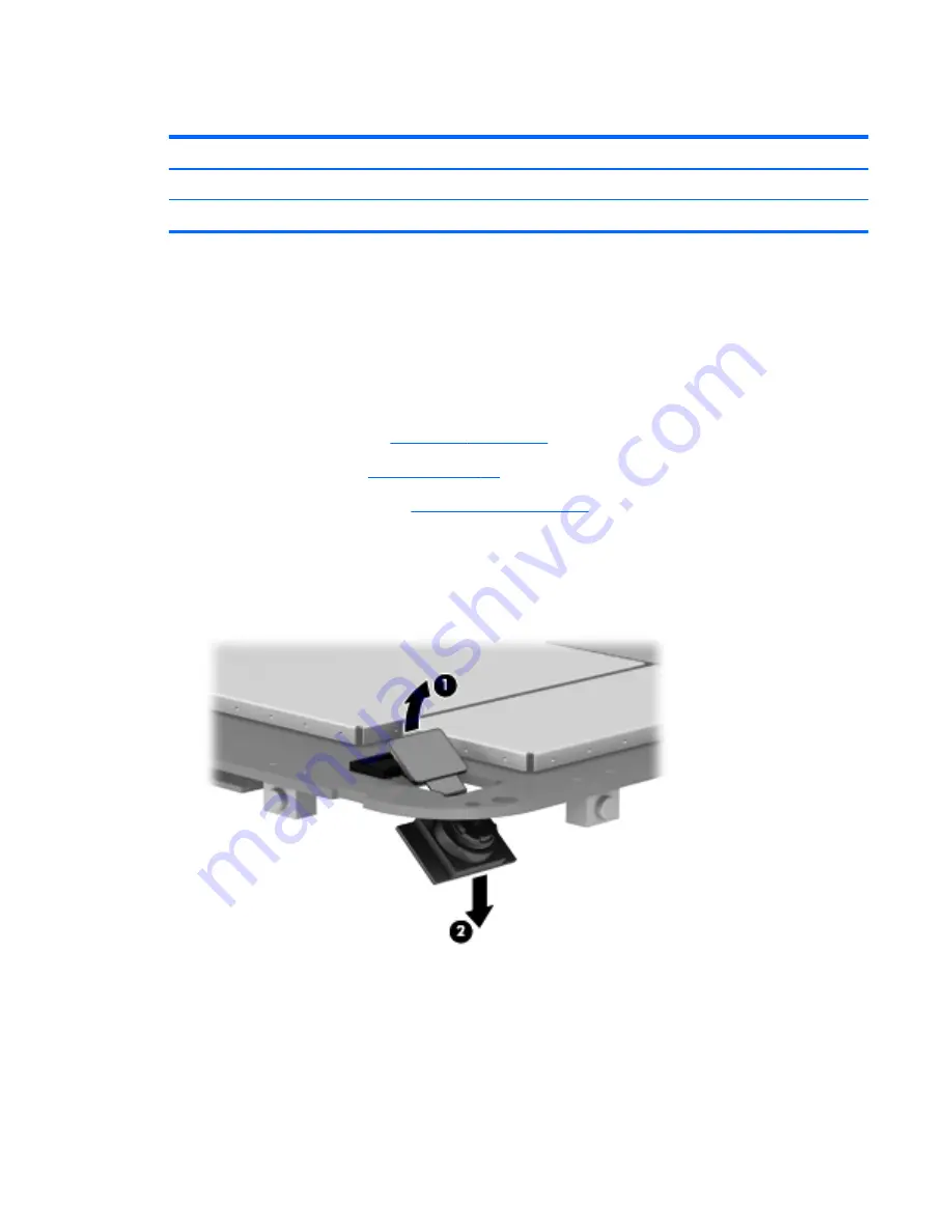
Remove the rear-facing webcam:

1.

Disconnect the rear-facing webcam cable 

(1)

 from the system board.

2.

Release the rear-facing webcam 

(2)

 from the opening in the system board.

3.

Remove the rear-facing webcam.

Remove the front-facing webcam:

1.

Turn the system board upside down with the front toward you.

Removal and replacement procedures

21

Summary of Contents for series 7

Page 1: ...HP Tablet 7 Maintenance and Service Guide ...

Page 2: ...otice The only warranties for HP products and services are set forth in the express warranty statements accompanying such products and services Nothing herein should be construed as constituting an additional warranty HP shall not be liable for technical or editorial errors or omissions contained herein First Edition April 2013 Document Part Number 725389 001 ...

Page 3: ...w another hard surface such as an adjoining optional printer or a soft surface such as pillows or rugs or clothing to block airflow Also do not allow the AC adapter to contact the skin or a soft surface such as pillows or rugs or clothing during operation The device and the AC adapter comply with the user accessible surface temperature limits defined by the International Standard for Safety of Inf...

Page 4: ...iv Safety warning notice ...

Page 5: ... Removal and replacement procedures preliminary requirements 9 Tools required 9 Service considerations 9 Plastic parts 9 Cables and connectors 10 Drive handling 10 Grounding guidelines 11 Electrostatic discharge damage 11 Packaging and transporting guidelines 12 Workstation guidelines 12 Removal and replacement procedures 14 Component replacement procedures 14 Rear cover 14 Battery 16 System board...

Page 6: ...he operating system 27 Back up and reset 27 Factory data reset 28 Android system recovery mode 28 6 Tablet specifications 29 7 Power cord set requirements 30 Requirements for all countries 30 Requirements for specific countries and regions 31 8 Recycling 32 Index 33 vi ...

Page 7: ...iMediaCard eMMC mass storage memory 16 GB and 32 GB in 169 pin thin profile fine pitch ball grid array TFBGA Audio and video Dual digital microphones TI class D IC audio amplifier Stereo speakers 0 3 MP front facing camera 3 0p MP rear facing camera Ports Audio 3 pin headset Charging micro USB SD Card micro SD Card USB micro USB Keys Power Volume down Volume up Power requirements Support for the f...

Page 8: ... 1 Headphone jack 6 Front camera 2 Internal microphone 7 Rear camera 3 Micro SD Card reader 8 Speaker and headphone volume 4 Power button 9 Speakers 2 5 WLAN antenna 10 Micro USB port for charging or connecting to tablet 2 Chapter 2 External component identification ...

Page 9: ...3 Illustrated parts catalog 3 ...

Page 10: ...er and product number of your tablet are located on the left edge of the tablet The model number of your tablet is located on the back of your tablet You may need the information when you travel internationally or when you contact support 4 Chapter 3 Illustrated parts catalog ...

Page 11: ...d with 16 GB of system memory 730355 001 In silver finish for use only on tablet models equipped with 16 GB of system memory 730354 001 In red finish for use only on tablet models equipped with 8 GB of system memory 727909 001 In silver finish for use only on tablet models equipped with 8 GB of system memory 727659 001 Tablet major components 5 ...

Page 12: ...6A dual core A9 1 60 GHz processor and 16 GB of system memory 729093 001 Equipped with an RK3066A dual core A9 1 60 GHz processor and 8 GB of system memory 727666 001 7 Front facing webcam 727667 001 8 Rear facing webcam includes cable 731533 001 Trim Kit includes 727661 001 9a Side trim 9b System board bracket 9c Volume control button actuator 10 Antenna board 727662 001 11 7 0 in LCD TFT TouchSc...

Page 13: ...ca 727660 001 For use in North America 727658 001 HP Tablet 7 tablet with TFT LCD TouchScreen Equipped with 16 GB of system memory in red finish for use in all countries and regions 732048 001 Equipped with 16 GB of system memory in silver finish for use in all countries and regions 732047 001 Equipped with 8 GB of system memory in red finish for use in all countries and regions 730930 001 Equippe...

Page 14: ...a 728938 001 10 W USB power adapter for use in Asia Pacific countries and regions and Japan 729092 001 HP Tablet 7 tablet with TFT LCD TouchScreen and 8 GB of system memory in silver finish for use in all countries and regions 729093 001 System board equipped with an RK3066A dual core A9 1 60 GHz processor and 16 GB of system memory includes battery shielding tape 729741 001 USB connector includes...

Page 15: ...Phillips P00 screw driver Torx T 4 screw driver Service considerations The following sections include some of the considerations that you must keep in mind during disassembly and assembly procedures NOTE As you remove each subassembly from the tablet place the subassembly and all accompanying screws away from the work area to prevent damage Plastic parts CAUTION Using excessive force during disass...

Page 16: ...ve shut down the tablet If you are unsure whether the tablet is off or in Hibernation turn the tablet on and then shut it down through the operating system Before handling a drive be sure that you are discharged of static electricity While handling a drive avoid touching the connector Before removing a diskette drive or optical drive be sure that a diskette or disc is not in the drive and be sure ...

Page 17: ...e these precautions Keep components in their electrostatic safe containers until you are ready to install them Before touching an electronic component discharge static electricity by using the guidelines described in this section Avoid touching pins leads and circuitry Handle electronic components as little as possible If you remove a component place it in an electrostatic safe container The follo...

Page 18: ...r materials are selected to avoid static charging When grounding is not possible use an ionizer to dissipate electric charges Workstation guidelines Follow these grounding workstation guidelines Cover the workstation with approved static shielding material Use a wrist strap connected to a properly grounded work surface and use properly grounded tools and equipment Use conductive field service tool...

Page 19: ...m resistance between the operator and ground To be effective the conductive must be worn in contact with the skin The following grounding equipment is recommended to prevent electrostatic damage Antistatic tape Antistatic smocks aprons and sleeve protectors Conductive bins and other assembly or soldering aids Nonconductive foam Conductive tabletop workstations with ground cords of one megohm resis...

Page 20: ...n silver finish for use only on tablet models equipped with 8 GB of system memory 727659 001 Before removing the disassembling the tablet follow these steps 1 Turn off the tablet If you are unsure whether the tablet is off or in Hibernation turn the tablet on and then shut it down through the operating system 2 Disconnect the power from the tablet by unplugging the power cord from the tablet 3 Dis...

Page 21: ...bezel is available using spare part number 731532 001 4 Separate the top edge 1 of the rear cover from the display assembly 5 Remove the rear cover 2 Reverse this procedure to install the keyboard Removal and replacement procedures 15 ...

Page 22: ...To reduce potential safety issues use only the battery provided with the tablet a replacement battery provided by HP or a compatible battery purchased from HP CAUTION Removing a battery that is the sole power source for the tablet can cause loss of information To prevent loss of information save your work or shut down the tablet through Windows before removing the battery Remove the battery 1 Disc...

Page 23: ...4 Remove the battery 5 Reverse this procedure to install the battery Removal and replacement procedures 17 ...

Page 24: ...ating system 2 Disconnect the power from the tablet by unplugging the power cord from the tablet 3 Disconnect all external devices from the tablet 4 Remove the rear cover see Rear cover on page 14 5 Remove the battery see Battery on page 16 WARNING To reduce potential safety issues use only the battery provided with the tablet a replacement battery provided by HP or a compatible battery purchased ...

Page 25: ... 1 Speaker cable 2 USB cable 3 X axis control cable 4 Y axis control cable 2 Remove the six Phillips PM1 75 4 0 screws that secure the system board to the display assembly 3 Lift the right side 1 of the system board until it rests at an angle Removal and replacement procedures 19 ...

Page 26: ...4 Remove the system board 2 by sliding it up and to the right at an angle Reverse this procedure to install the system board 20 Chapter 4 Removal and replacement procedures preliminary requirements ...

Page 27: ...ging the power cord from the tablet 3 Disconnect all external devices from the tablet 4 Remove the rear cover see Rear cover on page 14 5 Remove the battery see Battery on page 16 6 Remove the system board see System board on page 18 Remove the rear facing webcam 1 Disconnect the rear facing webcam cable 1 from the system board 2 Release the rear facing webcam 2 from the opening in the system boar...

Page 28: ...e the front facing webcam Reverse this procedure to install the webcams NOTE When installing the front facing webcam note that the connector is keyed and connects to the system board only one way 22 Chapter 4 Removal and replacement procedures preliminary requirements ...

Page 29: ...from the tablet by unplugging the power cord from the tablet 3 Disconnect all external devices from the tablet 4 Remove the rear cover see Rear cover on page 14 5 Remove the battery see Battery on page 16 Remove the USB connector 1 Disconnect the USB connector cable 1 from the system board 2 Remove the Phillips PM1 75 4 0 screw 2 that secures the USB connector to the display assembly 3 Remove the ...

Page 30: ... power from the tablet by unplugging the power cord from the tablet 3 Disconnect all external devices from the tablet 4 Remove the rear cover see Rear cover on page 14 5 Remove the battery see Battery on page 16 Remove the USB connector Detach the antenna board from the display assembly The antenna board is attached to the display assembly with double sided adhesive Reverse this procedure to insta...

Page 31: ...2 Disconnect the power from the tablet by unplugging the power cord from the tablet 3 Disconnect all external devices from the tablet 4 Remove the rear cover see Rear cover on page 14 5 Remove the battery see Battery on page 16 Remove the speakers 1 Disconnect the speaker cable 1 from the system board 2 Remove the two Phillips PM1 75 4 0 screws 2 that secure the speakers to the display assembly 3 ...

Page 32: ...lugging the power cord from the tablet 3 Disconnect all external devices from the tablet 4 Remove the rear cover see Rear cover on page 14 5 Remove the battery see Battery on page 16 Remove the side trim Remove the side trim 1 from the retaining clips built into the display assembly NOTE When the side trim is removed the volume control button actuator 2 is prone to slipping out of the side trim Ma...

Page 33: ...operating system will download system updates automatically and notify you when it is ready to install these updates If you want to update the operating system manually go to http www hp com support You can also set preferences for backing up and restoring your data in case of loss Back up and reset 1 To access Settings touch the All apps icon and then touch Settings 2 Under PERSONAL touch Back up...

Page 34: ...ollow the on screen instructions Android system recovery mode 1 Press the power button and then touch Power off 2 Press the power button and the volume up button at the same time 3 Press the volume up or volume down button to advance through the options and then press the power button to select one of the following options Reboot system now Apply update from ADB Update recover from SD card 28 Chap...

Page 35: ...onoperating 20 C to 60 C 4 F to 140 F Relative humidity noncondensing Operating 10 to 90 Nonoperating 5 to 95 Maximum altitude unpressurized Operating 15 m to 3 048 m 50 ft to 10 000 ft Nonoperating 15 m to 12 192 m 50 ft to 40 000 ft NOTE Applicable product safety standards specify thermal limits for plastic surfaces The device operates well within this range of temperatures 29 ...

Page 36: ...irements are applicable to all countries and regions The length of the power cord set must be at least 1 0 m 3 3 ft and no more than 2 0 m 6 5 ft All power cord sets must be approved by an acceptable accredited agency responsible for evaluation in the country or region where the power cord set will be used The power cord sets must have a minimum current capacity of 10 amps and a nominal voltage ra...

Page 37: ...st be a two pole grounding type with a NEMA 5 15P 15 A 125 V or NEMA 6 15P 15 A 250 V configuration 3 The appliance coupler flexible cord and wall plug must bear a T mark and registration number in accordance with the Japanese Dentori Law The flexible cord must be Type VCT or VCTF 3 conductor 1 00 mm conductor size The wall plug must be a two pole grounding type with a Japanese Industrial Standard...

Page 38: ...in general household waste Follow the local laws and regulations in your area for battery disposal HP encourages customers to recycle used electronic hardware HP original print cartridges and rechargeable batteries For more information about recycling programs see the HP Web site at http www hp com recycle 32 Chapter 8 Recycling ...

Page 39: ...roduct description 1 memory module product description 1 microphone product description 1 model name 1 O operating system product description 1 P packaging guidelines 12 plastic parts service considerations 9 ports product description 1 power adapter spare part numbers 7 8 power cord set requirements 30 power requirements product description 1 processor product description 1 product description au...

Page 40: ...nts 5 tablet spare part numbers 7 8 tools required 9 transporting guidelines 12 Trim Kit contents 7 spare part number 6 7 8 U USB cable extension spare part number 7 8 USB connector removal 23 spare part number 6 8 23 V video product description 1 volume control button actuator illustrated 7 location 26 W webcam removal 21 spare part numbers 6 8 21 workstation guidelines 12 34 Index ...

Page 41: ......

Reviews: