background image


Removal and replacement procedures  60 


CAUTION:

  Always install the processor parallel to the system board to avoid damage to the 

pins. 


5.


Close the processor retaining latch and the processor socket retaining bracket. 


6.


Clean the old thermal grease from the heatsink and the top of the processor with the alcohol swab. 
Allow the alcohol to evaporate before continuing. 

Summary of Contents for ProLiant DL385 G5p

Page 1: ...tic tools specifications and requirements for hardware components and software This guide is for an experienced service technician HP assumes you are qualified in the servicing of computer equipment trained in recognizing hazards in products and are familiar with weight and stability precautions Part Number 495671 004 April 2012 Edition 4 ...

Page 2: ...t forth in the express warranty statements accompanying such products and services Nothing herein should be construed as constituting an additional warranty HP shall not be liable for technical or editorial errors or omissions contained herein Microsoft Windows NT and Windows Server are U S registered trademarks of Microsoft Corporation AMD is a trademark of Advanced Micro Devices Inc ...

Page 3: ...Trusted Platform Module 30 Access panel 30 SAS hard drive blank 30 Hot plug SAS hard drive 31 Power supply blank 31 Optical drive cage 32 Systems Insight Display 33 Front right bezel 33 Front left bezel 34 Power supply backplane 35 Hot plug fan 36 Hard drive backplane 37 PCI riser cage 38 Air baffle 39 Fan cage 39 Expansion slot covers 40 Expansion boards 42 Half length expansion board 42 Full len...

Page 4: ...t panel LEDs and buttons 68 Systems Insight Display LEDs 69 Systems Insight Display LEDs and internal health LED combinations 69 Rear panel components 70 Rear panel LEDs and buttons 71 Non hot plug PCI riser board slot definitions 72 System board 73 System board components 73 System board switches 74 NMI functionality 74 DIMM slots 75 Hard drive numbering 75 SAS and SATA hard drive LEDs 75 SAS and...

Page 5: ...n will help you over the telephone HP specifies in the materials shipped with a replacement CSR part whether a defective part must be returned to HP In cases where it is required to return the defective part to HP you must ship the defective part back to HP within a defined period of time normally five 5 business days The defective part must be returned with the associated documentation in the pro...

Page 6: ...ine la société de courses ou le transporteur à utiliser Pour plus d informations sur le programme CSR de HP contactez votre Mainteneur Agrée local Pour plus d informations sur ce programme en Amérique du Nord consultez le site Web HP http www hp com go selfrepair Service de garantie pièces seules Votre garantie limitée HP peut inclure un service de garantie pièces seules Dans ce cas les pièces de ...

Page 7: ... Self Repair um Reparaturzeiten zu minimieren und höhere Flexibilität beim Austausch defekter Bauteile zu ermöglichen Wenn HP oder ein HP Servicepartner bei der Diagnose feststellt dass das Produkt mithilfe eines CSR Teils repariert werden kann sendet Ihnen HP dieses Bauteil zum Austausch direkt zu CSR Teile werden in zwei Kategorien unterteilt Zwingend Teile für die das Customer Self Repair Verfa...

Page 8: ...tegorías Obligatorio componentes para los que la reparación por parte del usuario es obligatoria Si solicita a HP que realice la sustitución de estos componentes tendrá que hacerse cargo de los gastos de desplazamiento y de mano de obra de dicho servicio Opcional componentes para los que la reparación por parte del usuario es opcional Estos componentes también están diseñados para que puedan ser r...

Page 9: ...orieën CSR onderdelen Verplicht Onderdelen waarvoor reparatie door de klant verplicht is Als u HP verzoekt deze onderdelen voor u te vervangen worden u voor deze service reiskosten en arbeidsloon in rekening gebracht Optioneel Onderdelen waarvoor reparatie door de klant optioneel is Ook deze onderdelen zijn ontworpen voor reparatie door de klant Als u echter HP verzoekt deze onderdelen voor u te v...

Page 10: ...ependendo do tipo de serviço de garantia destinado ao produto OBSERVAÇÃO Algumas peças da HP não são projetadas para o reparo feito pelo cliente A fim de cumprir a garantia do cliente a HP exige que um técnico autorizado substitua a peça Essas peças estão identificadas com a marca No Não no catálogo de peças ilustrado Conforme a disponibilidade e o local geográfico as peças CSR serão enviadas no p...

Page 11: ...Customer self repair 11 No caso desse serviço a substituição de peças CSR é obrigatória Se desejar que a HP substitua essas peças serão cobradas as despesas de transporte e mão de obra do serviço ...

Page 12: ...Customer self repair 12 ...

Page 13: ...Customer self repair 13 ...

Page 14: ...Customer self repair 14 ...

Page 15: ...Customer self repair 15 ...

Page 16: ...061 001 Mandatory1 3 Hardware kit 496058 001 Mandatory1 a Fan blank 507009 001 b Optical blank 505953 001 c Heatsink blank 507010 001 d Power supply blank 499244 001 e PCI expansion slot blank full length 507011 001 f PCI expansion slot blank short low profile 507012 001 g PCI retainer 509084 001 h PCI retainer top 509085 001 i PCI retainer end 509086 001 j PCI retainer removable 509087 001 k T 10...

Page 17: ...nçues pour permettre au client d effectuer lui même la réparation Pour que la garantie puisse s appliquer HP exige que le remplacement de la pièce soit effectué par un Mainteneur Agréé Ces pièces sont identifiées par la mention Non dans le Catalogue illustré 1 Mandatory Obbligatorie Parti che devono essere necessariamente riparate dal cliente Se il cliente ne affida la riparazione ad HP deve soste...

Page 18: ...reparatie door de klant Als u echter HP verzoekt deze onderdelen voor u te vervangen kunnen daarvoor extra kosten in rekening worden gebracht afhankelijk van het type garantieservice voor het product 3 No Nee Sommige HP onderdelen zijn niet ontwikkeld voor reparatie door de klant In verband met de garantievoorwaarden moet het onderdeel door een geautoriseerde Service Partner worden vervangen Deze ...

Page 19: ...hard drive cage 463174 001 496075 001 Mandatory1 17 Processor a 2 3 GHz AMD Opteron Model 2376 495643 003 502922 001 Optional2 b 2 4 GHz AMD Opteron Model 2378 495643 002 500514 001 Optional2 c 2 5 GHz AMD Opteron Model 2380 495643 001 500515 001 Optional2 d 2 6 GHz AMD Opteron Model 2382 496543 004 505635 001 Optional2 e 2 7 GHz AMD Opteron Model 2384 495643 005 505917 001 Optional2 f 2 9 GHz AMD...

Page 20: ...ECC RoHS 499277 061 501158 001 Mandatory1 d 8 GB PC2 5300 registered DDR2 405478 071 432671 001 Mandatory1 Cables 26 SAS backplane cable 83 8 cm 33 0 in 463184 001 496070 001 Mandatory1 27 SATA cable 484355 005 496071 001 Mandatory1 28 I O cable 463182 001 496072 001 Mandatory1 29 Mini SAS cable 495973 005 507692 001 Mandatory1 30 HD power cable 463184 002 514217 001 Mandatory1 31 AC power cord 14...

Page 21: ...ervice vous seront facturés 2 Optional Facultatif Pièces pour lesquelles la réparation par le client est facultative Ces pièces sont également conçues pour permettre au client d effectuer lui même la réparation Toutefois si vous demandez à HP de remplacer ces pièces l intervention peut ou non vous être facturée selon le type de garantie applicable à votre produit 3 No Non Certaines pièces HP ne so...

Page 22: ...ustomer Self Repair verplicht is Als u HP verzoekt deze onderdelen te vervangen komen de reiskosten en het arbeidsloon voor uw rekening 2 Optional Optioneel Onderdelen waarvoor reparatie door de klant optioneel is Ook deze onderdelen zijn ontworpen voor reparatie door de klant Als u echter HP verzoekt deze onderdelen voor u te vervangen kunnen daarvoor extra kosten in rekening worden gebracht afha...

Page 23: ...Illustrated parts catalog 23 ...

Page 24: ...iners until they arrive at static free workstations Place parts on a grounded surface before removing them from their containers Avoid touching pins leads or circuitry Always be properly grounded when touching a static sensitive component or assembly Server warnings and cautions Before installing a server be sure that you understand the following warnings and cautions WARNING To reduce the risk of...

Page 25: ...to support the server and gain access to internal components For more information about telco rack solutions refer to the RackSolutions com website http www racksolutions com hp Power down the server on page 26 If you must remove a server from a rack or a non hot plug component from a server power down the server Remove the server from the rack on page 27 If the rack environment cabling configurat...

Page 26: ...stem power Portions of the power supply and some internal circuitry remain active until AC power is removed IMPORTANT If installing a hot plug device it is not necessary to power down the server 1 Back up the server data 2 Shut down the operating system as directed by the operating system documentation NOTE If the operating system automatically places the server in Standby mode omit the next step ...

Page 27: ...6 2 Extend the server from the rack on page 25 3 Disconnect the cabling and remove the server from the rack For more information refer to the documentation that ships with the rack mounting option 4 Place the server on a sturdy level surface Access the product rear panel Cable management arm with left hand swing To access the server rear panel 1 Remove the cable arm retainer ...

Page 28: ... To access some components you may need to remove the cable management arm To access the product rear panel components open the cable management arm 1 Power down the server on page 26 2 Swing open the cable management arm 3 Remove the cables from the cable trough 4 Remove the cable management arm Hot plug power supply ...

Page 29: ...ct rear panel on page 27 3 Disconnect the power cord from the power supply 4 Remove the hot plug power supply WARNING To reduce the risk of electric shock or damage to the equipment do not connect the power cord to the power supply until the power supply is installed To replace the component 1 Slide the hot plug power supply into the power supply bay 2 Connect the power cord to the power supply 3 ...

Page 30: ... board Access panel WARNING To reduce the risk of personal injury from hot surfaces allow the drives and the internal system components to cool before touching them CAUTION For proper cooling do not operate the server without the access panel baffles expansion slot covers or blanks installed If the server supports hot plug components minimize the amount of time the access panel is open To remove t...

Page 31: ...tus of the drive from the hot plug SAS hard drive LED combinations SAS and SATA hard drive LED combinations on page 76 2 Back up all server data on the hard drive 3 Remove the hard drive To replace the component reverse the removal procedure Power supply blank To remove the component CAUTION To prevent improper cooling and thermal damage do not operate the server unless all bays are populated with...

Page 32: ...To prevent improper cooling and thermal damage do not operate the server unless all bays are populated with either a component or a blank 1 Power down the server on page 26 2 Extend the server from the rack on page 25 3 Remove the access panel Access panel on page 30 4 Disconnect the cables from the optical drive 5 Remove the optical drive cage ...

Page 33: ... panel Access panel on page 30 4 Remove the PCI riser cage PCI riser cage on page 38 5 Remove the air baffle Air baffle on page 39 6 Disconnect the Systems Insight Display cable 7 Remove the Systems Insight Display To replace the component reverse the removal procedure Front right bezel To remove the component 1 Extend or remove the server from the rack Remove the server from the rack on page 27 E...

Page 34: ...e 26 2 Extend or remove the server from the rack Remove the server from the rack on page 27 Extend the server from the rack on page 25 3 Remove the access panel Access panel on page 30 4 Remove the PCI riser cage PCI riser cage on page 38 5 Remove the air baffle Air baffle on page 39 6 Extend or remove the Systems Insight Display Systems Insight Display on page 33 7 Disconnect the System Insight D...

Page 35: ... remove the component 1 Power down the server on page 26 2 Remove all power supplies Hot plug power supply on page 28 3 Extend or remove the server from the rack Remove the server from the rack on page 27 Extend the server from the rack on page 25 4 Remove the access panel Access panel on page 30 5 Remove the power supply backplane To replace the component reverse the removal procedure ...

Page 36: ...tdown is a hardware controlled function and it overrides any firmware or software actions In the operating system o The Health Driver performs an orderly shutdown if it detects a cautionary temperature level If the server detects a critical temperature level before the orderly shutdown occurs the server performs an immediate shutdown Additionally the Health Driver performs an orderly shutdown if m...

Page 37: ...mal damage To replace the component reverse the removal procedure Hard drive backplane To remove the component 1 Power down the server on page 26 2 Extend or remove the server from the rack Remove the server from the rack on page 27 Extend the server from the rack on page 25 3 Remove the access panel Access panel on page 30 4 Remove all hot plug hard drives Hot plug SAS hard drive on page 31 5 Dis...

Page 38: ... For proper cooling do not operate the server without the access panel baffles expansion slot covers or blanks installed If the server supports hot plug components minimize the amount of time the access panel is open 1 Power down the server on page 26 2 Extend the server from the rack on page 25 3 Remove the access panel Access panel on page 30 4 Remove the PCI riser cage ...

Page 39: ...emove the access panel Access panel on page 30 4 Remove the PCI riser cage PCI riser cage on page 38 CAUTION Do not detach the cable that connects the battery pack to the cache module Detaching the cable causes any unsaved data in the cache module to be lost 5 Remove the battery pack from the air baffle Removing the battery pack on page 45 6 Remove the air baffle To replace the component reverse t...

Page 40: ... expansion boards power down the server and remove all AC power cords before removing or installing the PCI riser cage CAUTION For proper cooling do not operate the server without the access panel baffles expansion slot covers or blanks installed If the server supports hot plug components minimize the amount of time the access panel is open 1 Power down the server on page 26 2 Extend the server fr...

Page 41: ...placement procedures 41 o To remove slot cover 1 or 4 push in on the retainer to release it and then slide out the cover o To remove slot covers 2 and 3 lift up on the latch remove the latch and then remove the cover ...

Page 42: ...xpansion board To remove the component 1 Power down the server on page 26 2 Extend the server from the rack on page 25 3 Remove the access panel Access panel on page 30 4 Disconnect any external cables that are connected to the expansion board 5 Remove the PCI riser cage PCI riser cage on page 38 6 Disconnect any internal cables that are connected to the expansion board ...

Page 43: ...ponent 1 Power down the server on page 26 2 Extend the server from the rack on page 25 3 Remove the access panel Access panel on page 30 4 Disconnect any external cables that are connected to the expansion board 5 Remove the PCI riser cage PCI riser cage on page 38 6 Disconnect any internal cables that are connected to the expansion board 7 Remove the expansion board ...

Page 44: ...ng the cable causes any unsaved data in the cache module to be lost Removing the cache module To remove the component 1 Power down the server on page 26 2 Extend or remove the server from the rack Remove the server from the rack on page 27 Extend the server from the rack on page 25 3 Remove the access panel Access panel on page 30 4 Remove the PCI riser cage PCI riser cage on page 38 5 Remove the ...

Page 45: ...the information about protecting against electrostatic discharge Preventing electrostatic discharge on page 24 1 Perform one of the following o Set up a recovery server station using an identical server model Do not install any internal drives or BBWC in this server HP recommends this option o Find a server that has enough empty drive bays to accommodate all the drives from the failed server and t...

Page 46: ...nd battery pack in the recovery server 5 Power up the recovery server A 1759 POST message is displayed stating that valid data was flushed from the cache This data is now stored on the drives in the recovery server You can now transfer the drives and controller if one was used to another server Heatsink To remove the heatsink 1 Power down the server on page 26 2 Extend the server from the rack on ...

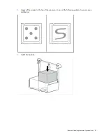
Page 47: ...Removal and replacement procedures 47 2 Apply all the grease to the top of the processor in one of the following patterns to ensure even distribution 3 Install the heatsink ...

Page 48: ...ove the component 1 Power down the server on page 26 2 Access the product rear panel on page 27 3 Remove all power supplies Hot plug power supply on page 28 4 Remove the server from the rack on page 27 5 Remove the access panel Access panel on page 30 6 Remove the PCI riser cage PCI riser cage on page 38 7 Remove the air baffle Air baffle on page 39 8 Remove the power supply backplane Power supply...

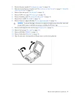
Page 49: ...rocessor in this server CAUTION To prevent possible server malfunction and damage to the equipment multiprocessor configurations must contain processors with the same part number To remove a processor 1 Power down the server on page 26 2 Extend the server from the rack on page 25 3 Remove the access panel Access panel on page 30 4 Remove the PCI riser cage PCI riser cage on page 38 5 Remove the ai...

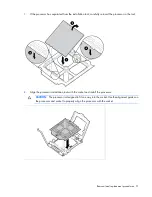
Page 50: ...or To replace a processor CAUTION The pins on the processor socket are very fragile Any damage to them may require replacing the system board CAUTION Failure to completely open the processor locking lever prevents the processor from seating during installation leading to hardware damage IMPORTANT Be sure the processor remains inside the processor installation tool ...

Page 51: ...ol carefully re insert the processor in the tool 2 Align the processor installation tool with the socket and install the processor CAUTION The processor is designed to fit one way into the socket Use the alignment guides on the processor and socket to properly align the processor with the socket ...

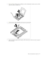
Page 52: ...on tool clicks and separates from the processor and then remove the processor installation tool 4 Close the processor retaining bracket and the processor retaining latch 5 Clean the old thermal grease from the heatsink with the alcohol swab Allow the alcohol to evaporate before continuing ...

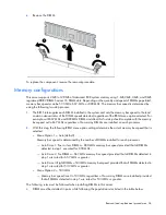
Page 53: ...I riser cage on page 38 11 Install the access panel Access panel on page 30 12 Install the server into the rack 13 Power up the server DIMMs To remove the component 1 Power down the server on page 26 2 Extend or remove the server from the rack Remove the server from the rack on page 27 Extend the server from the rack on page 25 3 Remove the access panel Access panel on page 30 4 Remove the PCI ris...

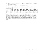
Page 54: ... how many DIMMs are installed on each processor 2 With this step the following RBSU menu option settings determine the actual memory bus speed that is selected o Menu Option 1 Auto default Memory bus speed is determined by the number of DIMMs installed for each processor Auto Case 1 Four or less DIMMs 800 MHz memory bus speed provided that all DIMMs detected in step 1 are rated for 800 MHz Auto Ca...

Page 55: ...1st 2nd 3rd 4th 2 processors 1st 2nd 3rd 4th 1st 2nd 3rd 4th Advanced ECC memory is the memory protection mode for this server In Advanced ECC the server does not fail because of correctable memory errors The server provides notification if the level of correctable errors exceeds a pre defined threshold rate Advanced ECC provides additional protection over standard ECC because it is possible to co...

Page 56: ...eratures higher than 60 C 140 F Do not disassemble crush puncture short external contacts or dispose of in fire or water Replace only with the spare designated for this product To remove the component 1 Power down the server on page 26 2 Extend the server from the rack on page 25 3 Remove the access panel Access panel on page 30 4 Remove the PCI riser cage PCI riser cage on page 38 5 Remove the ai...

Page 57: ...battery pack on page 45 7 Remove the air baffle Air baffle on page 39 8 Remove the power supply backplane Power supply backplane on page 35 CAUTION To prevent damage to the server or expansion boards power down the server and remove all AC power cords before removing or installing the PCI riser cage 9 Remove the hot plug fans from the fan cage Hot plug fan on page 36 10 Remove the fan cage Fan cag...

Page 58: ...e the processor when removing the processor from the socket CAUTION To avoid damage to the processor Handle the processor only by the edges Do not touch the bottom of the processor especially the contact area 15 Disconnect all cables connected to the system board 16 Remove the retaining screw at the rear of the chassis 17 Loosen the system board thumbscrews 18 Remove the power supply cage assembly...

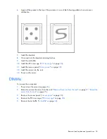
Page 59: ...ard a Remove the processor socket protective cover b Open the processor retaining latch and the processor socket retaining bracket 3 Install the processor socket cover onto the processor socket of the failed system board 4 Install the processor on the spare system board CAUTION The processor is designed to fit one way into the socket Use the alignment guides on the processor and socket to properly...

Page 60: ...lel to the system board to avoid damage to the pins 5 Close the processor retaining latch and the processor socket retaining bracket 6 Clean the old thermal grease from the heatsink and the top of the processor with the alcohol swab Allow the alcohol to evaporate before continuing ...

Page 61: ...umber and the product ID 1 During the server startup sequence press the F9 key to access RBSU 2 Select the System Options menu 3 Select Serial Number The following warning is displayed WARNING WARNING WARNING The serial number is loaded into the system during the manufacturing process and should NOT be modified This option should only be used by qualified service personnel This value should always...

Page 62: ...Cabling 62 Cabling SAS hard drive cabling Battery cabling for BBWC ...

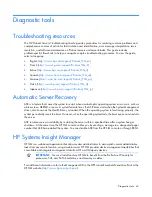
Page 63: ...fail safe timer the ASR timer starts when the System Management driver also known as the Health Driver is loaded When the operating system is functioning properly the system periodically resets the timer However when the operating system fails the timer expires and restarts the server ASR increases server availability by restarting the server within a specified time after a system hang or shutdown...

Page 64: ...es iLO 2 independent of the host server and its operating system The iLO 2 subsystem provides remote access to any authorized network client sends alerts and provides other server management functions Using iLO 2 you can Remotely power up power down or reboot the host server Send alerts from iLO 2 regardless of the state of the host server Access advanced troubleshooting features through the iLO 2...

Page 65: ...nfiguration activities that can include the following Configuring system devices and installed options Enabling and disabling system features Displaying system information Selecting the primary boot controller Configuring memory options Language selection For more information on RBSU see the HP ROM Based Setup Utility User Guide on the Documentation CD or the HP website http www hp com support sma...

Page 66: ...dows 2000 Windows Server 2003 Novell Netware and Linux operating systems IMPORTANT This utility supports operating systems that may not be supported by the server For operating systems supported by the server see the HP website http www hp com support Integrates with other software maintenance deployment and operating system tools Automatically checks for hardware firmware and operating system dep...

Page 67: ...edundant ROM support The server has a 4 MB ROM that acts as two separate 2 MB ROMs In the standard implementation one side of the ROM contains the current ROM program version while the other side of the ROM contains a backup version NOTE The server ships with the same version programmed on each side of the ROM ...

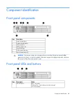
Page 68: ...ical drive bay 7 Quick release levers 2 CAUTION For proper cooling do not operate the server without the access panel baffles expansion slot covers or blanks installed If the server supports hot plug components minimize the amount of time the access panel is open Front panel LEDs and buttons Item Description Status 1 UID LED button Blue Activated Flashing blue System being remotely managed Off Dea...

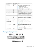
Page 69: ...lied Off Power cord not attached or power supply failure Systems Insight Display LEDs Item Description Status 1 NIC LEDs Off No link to network Flashing green Network link and activity Green Network link 2 Power Cap LED Off Server in standby Flashing amber Power cap exceeded Green Power cap configured All other LEDs Off Normal Amber Failure Systems Insight Display LEDs and internal health LED comb...

Page 70: ...DIMMs Isolate the failed DIMM by replacing each DIMM in a bank with a known working DIMM Overtemperature amber Amber The Health Driver has detected a cautionary temperature level Red The server has detected a hardware critical temperature level Fan amber Amber One fan is failed or removed Red Two or more fans have failed or are missing Power supply amber Red Only one power supply installed and pow...

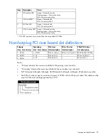
Page 71: ... 1 connector 14 NIC 2 connector 15 Mouse connector Green 16 Keyboard connector Purple 17 Serial connector 18 iLO 2 connector 19 NIC 3 connector 20 NIC 4 connector Rear panel LEDs and buttons Item Description Status 1 Power supply 2 power LED Green Normal Off System is off or power supply has failed 2 Power supply 1 power LED Green Normal Off System is off or power supply has failed 3 UID LED butto...

Page 72: ...lot form factor Secondary slot form factor PCIe riser slot description PCIe x16 riser slot description PCIe PCI X riser slot description 1 FL FH 4 FL FH PCIe x16 8 4 1 PCIe x16 16 8 4 1 PCI X 64bit 133MHz 2 HL FH 5 LP PCIe x8 4 1 PCIe x16 8 4 1 3 HL FH 6 LP PCIe x8 4 1 PCIe x8 4 1 Notes Primary denotes the risers are installed in the primary riser connector Secondary denotes the risers are install...

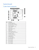
Page 73: ...ive connector 6 USB connector 7 System battery connector 8 TPM connector 9 NMI jumper 10 System maintenance switch 11 Power supply backplane connector 12 Processor 1 socket 13 Primary riser connector 14 Secondary riser connector 15 Diagnostic LEDs 16 Processor 2 socket 17 Processor 2 DIMM slots 18 Fan 6 connector 19 Fan 5 connector 20 Fan 4 connector 21 Fan 3 connector 22 Fan 2 connector 23 Fan 1 ...

Page 74: ...tion S7 S8 Diagnostic LEDs Off Off Port 85 Off On Port 84 On Off iLO 2 NMI functionality An NMI crash dump enables administrators to create crash dump files when a system is hung and not responding to traditional debug mechanisms Crash dump log analysis is an essential part of diagnosing reliability problems such as hangs in operating systems device drivers and applications Many crashes freeze a s...

Page 75: ...Component identification 75 DIMM slots DIMM slots are identified by the numbers 1 through 16 and paired banks are identified by the letters A through H Hard drive numbering SAS and SATA hard drive LEDs ...

Page 76: ...en received for this drive To minimize the risk of data loss do not replace the drive until the expansion or migration is complete Flashing regularly 1 Hz Off Do not remove the drive Removing a drive may terminate the current operation and cause data loss The drive is rebuilding erasing or it is part of an array that is undergoing capacity expansion or stripe migration Flashing irregularly Amber f...

Page 77: ...nstalled and power might be connected Battery pack LEDs Item ID Color Description 1 Green System Power LED This LED glows steadily when the system is powered up and 12 V system power is available This power supply is used to maintain the battery charge and provide supplementary power to the cache microcontroller ...

Page 78: ...roller to communicate One blink per second The battery pack is below the minimum charge level and is being charged Features that require a battery such as write cache capacity expansion stripe size migration and RAID migration are temporarily unavailable until charging is complete The recharge process takes between 15 minutes and two hours depending on the initial capacity of the battery Steady gl...

Page 79: ...Component identification 79 For more information see Hot plug fan operation Hot plug fan on page 36 ...

Page 80: ... allowed Storage maximum humidity of 95 is based on a maximum temperature of 45 C 113 F Altitude maximum for storage corresponds to a pressure minimum of 70 KPa Server specifications Specification Value Dimensions Height 8 85 cm 3 45 in Depth 69 20 cm 27 25 in Width 44 54 cm 17 54 in Weight maximum 27 27 kg 60 12 lb Weight no drives installed 21 36 kg 47 10 lb Input requirements Rated input voltag...

Page 81: ...ww3 hp com configurator CD ROM drive specifications Specification Value Disk formats CD ROM modes 1 and 2 mixed mode audio and data combined CD DA Photo CD single multiple session CD XA ready CDi ready Capacity 550 MB mode 1 12 cm 640 MB mode 2 12 cm Block size 2368 2352 bytes mode 0 2352 2340 2336 2048 bytes mode 1 2352 2340 2336 2048 bytes mode 2 Dimensions Height 12 7 mm 0 50 in Depth 132 08 mm...

Page 82: ...048 bytes mode 1 2352 2340 2336 2048 bytes mode 2 2048 bytes DVD Dimensions Height 12 7 mm 0 50 in Depth 132 08 mm 5 20 in Width 132 08 mm 5 20 in Weight 0 34 kg 0 75 lb Data transfer rate Sustained 4463 10 800 KB s 8X CAV DVD mode 150 KB s sustained 1X CD ROM 1552 3600 KB s 24X CAV CD ROM Burst 16 6 MB s with DMA support Access times typical Full stroke 200 ms CD 300 ms DVD Random 110 ms CD 180 m...

Page 83: ...B SATA drive Capacity 36 420 MB 73 408 MB 60 022 MB Height 15 mm 15 mm 9 mm Interface SAS SAS Serial ATA Transfer rate 3 GB sec 3 GB sec 1 5 GB sec Rotational speed 10 000 rpm 10 000 rpm 5 400 rpm Bytes per sector 512 512 512 Logical blocks 71 132 960 143 374 737 117 231 408 Operating temperature 10 C to 35 C 50 F to 95 F 10 C to 35 C 50 F to 95 F 10 C to 35 C 50 F to 95 F ...

Page 84: ...ttery backed write cache DDR double data rate iLO Integrated Lights Out IML Integrated Management Log NMI non maskable interrupt NVRAM non volatile memory ORCA Option ROM Configuration for Arrays PCIe peripheral component interconnect express PCI X peripheral component interconnect extended POST Power On Self Test ...

Page 85: ...Acronyms and abbreviations 85 RBSU ROM Based Setup Utility RDP Rapid Deployment Pack SAS serial attached SCSI SATA serial ATA TPM trusted platform module UID unit identification USB universal serial bus ...

Page 86: ...oviding documentation that meets your needs To help us improve the documentation send any errors suggestions or comments to Documentation Feedback mailto docsfeedback hp com Include the document title and part number version number or the URL when submitting your feedback ...

Page 87: ...epair 5 customer self repair CSR 5 D deployment software 65 diagnostic tools 63 65 66 diagnostics utility 66 DIMMs 53 54 75 diskette image creation 65 drive LEDs 75 drives 31 76 83 DVD ROM drive 82 E electrostatic discharge 24 environmental specifications 80 expansion boards 42 expansion slot covers 40 expansion slot covers removing 40 expansion slots 70 71 extending server from rack 25 F fan brac...

Page 88: ...power supply blank 31 power supply cage assembly 48 power supply LEDs 71 powering down 26 preparation procedures 25 processors 49 R RBSU ROM Based Setup Utility 65 rear components 70 rear panel components 70 rear panel connectors 70 rear panel LEDs 71 rear panel accessing 27 removal and replacement procedures 24 removing server from rack 27 removing the access panel 30 resetting the system 74 ROM ...

Page 89: ... racks 25 27 tools 63 TPM Trusted Platform Module 30 troubleshooting 63 Trusted Platform Module TPM 30 U UID LED 68 71 74 USB connectors 68 70 utilities 63 utilities deployment 65 V video connector 68 70 W warnings 24 ...

Reviews: