background image


Removal and replacement procedures  48 

3.


Remove the hot-plug power supply. 


To replace the component: 


WARNING:  To reduce the risk of electric shock or damage to the equipment, do not 

connect the power cord to the power supply until the power supply is installed.


1.


Slide the hot-plug power supply into the power supply bay. 

2.


Connect the power cord to the power supply. 

3.


Install the cable management arm, if removed. ("

Access the product rear panel

" on page 

21

4.


Route the power cord through the cable management arm or power cord anchor. 


NOTE:

  If using the power cord anchor, be sure to leave enough slack in the power cord so that the 

redundant power supply can be removed without disconnecting the power cord from the primary power 
supply. 

5.


Close the cable management arm. 

6.


Connect the power cord to the power source.  

7.


Be sure that the power supply LED is green ("

Rear panel LEDs and buttons

" on page 

78

). 

8.


Be sure that the front panel external health LED is green ("

Front panel LEDs and buttons

" on page 

76

). 


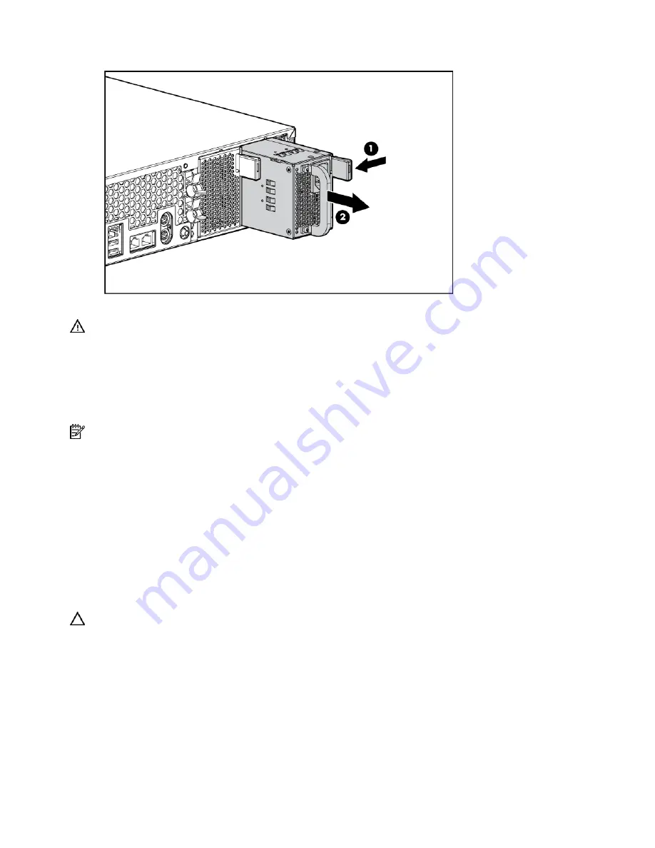
Power supply blank 

To remove the component: 


CAUTION:

  To prevent improper cooling and thermal damage, do not operate the server unless all bays 

are populated with either a component or a blank.  

1.


Do one of the following: 


If the cable management arm is hinged on the left side, proceed by opening the cable 
management arm ("

Cable management arm with left-hand swing

" on page 

21

). 


If the cable management arm is hinged on the right side, proceed by removing the cable 
management arm ("

Non-hot-plug procedures

" on page 

22

). 

2.


Remove the power supply blank. 

Summary of Contents for ProLiant DL380 G4 DPSS

Page 1: ...HP ProLiant DL380 Generation 4 Server Maintenance and Service Guide May 2006 Eighth Edition Part Number 359226 008 ...

Page 2: ...rein Microsoft Windows and Windows NT are U S registered trademarks of Microsoft Corporation Intel and Xeon are trademarks or registered trademarks of Intel Corporation or its subsidiaries in the United States and other countries Linux is a U S registered trademark of Linus Torvalds May 2006 Eighth Edition Part Number 359226 008 Audience assumptions This guide is for an experienced service technic...

Page 3: ...es 22 Access panel 22 DVD CD ROM drive 22 DVD CD ROM drive ejector assembly 23 Diskette drive option 24 Front bezel 24 Front fan bracket 25 Rear fan bracket 26 Battery backed write cache procedures 26 PCI riser cage door latch 30 PCI riser cage 31 Expansion board 31 Expansion slot cover 32 Expansion board ejector divider 33 PCI slot release lever 34 PCI lightpipe and cover 35 Power converter modul...

Page 4: ...B cabling 64 DVD CD ROM drive cabling 65 Diskette drive cabling 65 Power button LED cabling 66 Optional PCI Hot Plug backplane cabling 66 RILOE II cabling 67 Internal power cabling 67 External storage cabling 68 Diagnostic tools 69 Troubleshooting resources 69 Array Diagnostic Utility 69 Automatic Server Recovery 69 HP Insight Diagnostics 70 Integrated Management Log 70 Survey Utility 70 HP System...

Page 5: ...ns 88 PCI riser cage LED 89 Remote management connector 89 Internal PCI Hot Plug LEDs and button 90 Identifying hot plug fans 90 Hot plug fan LED 91 Power converter module LED 92 Battery backed write cache LEDs 92 Battery backed write cache LED statuses 93 Specifications 94 Server specifications 94 Environmental specifications 94 Hot plug power supply calculations 95 DDR2 SDRAM DIMM specifications...

Page 6: ...gnose and assess whether a replacement part is required to address a system problem The specialist will also determine whether you can replace the part Replacement parts are express shipped Most in stock parts are shipped the very same day you contact HP You may be required to send the defective part back to HP unless otherwise instructed Available for most HP products currently under warranty or ...

Page 7: ...al spare part number Modified spare part number Customer self repair 1 Access panel 359244 001 Yes 2 Front bezel 359245 001 Yes 3 Tape drive blank 367666 001 Yes 4 Hard drive blank 122759 001 Yes 5 Diskette drive slot cover see Plastics Kit Item 28k 6 Power supply blank 359246 001 Yes ...

Page 8: ...ent 406393 001 Yes 11 PCI riser cages a PCI riser cage with non hot plug PCI X standard 359248 001 See requirement 411020 001 Yes b PCI riser cage with non hot plug PCI Express optional 359259 001 See requirement 411021 001 Yes c PCI riser cage with PCI X hot plug optional 359260 001 See requirement 411022 001 Yes 12 Processor assemblies a 3 0 GHz Intel Xeon 1 MB L2 cache 378006 001 Yes b 3 2 GHz ...

Page 9: ...03934 001 Yes Boards 13 PPM 12 V 81 A 347884 001 Yes 14 Smart Array 6i memory module 351518 001 Yes 15 System board a System board single core processor support with processor cages and system battery 359251 001 Yes b System board dual core processor support SCSI with processor cages and system battery for use with Intel Xeon dual core processor only 404715 001 See requirement 411028 001 Yes 16 Po...

Page 10: ...able kit 366063 001 a Diskette drive cable Yes b CD multibay adaptor cable Yes c USB cable and connector Yes Rack mounting hardware 26 2U Quick Deploy Rail System 359254 001 Yes Miscellaneous 27 Hardware kit 228527 001 a Screws T 15 flat head Yes b Expansion slot cover Yes c Screws 6 32 Yes 28 Plastics kit 359720 001 a PCI slot release lever Yes b PCI lightpipe rear Yes c PCI lightpipe cover Yes d...

Page 11: ... See requirement 413388 001 Yes Options 41 Battery Backed Write Cache battery pack 307132 001 Yes 42 Battery Backed Write Cache battery bracket with cable 349989 001 Yes 43 SCSI Ultra320 universal hot plug hard drive a 72 8 GB 10 000 rpm 289042 001 See requirement 404709 001 Yes b 146 8 GB 10 000 rpm 289044 001 See requirement 404708 001 Yes c 300 GB 10 000 rpm 351126 001 See requirement 404701 00...

Page 12: ...t performance or functionality of the unit Directive 2002 95 EC restricts the use of lead mercury cadmium hexavalent chromium PBBs and PBDEs in electronic products Mechanical components SAS model Item Description Original spare part number Modified spare part number Customer self repair 1 Access panel 359244 001 Yes 2 Front bezel 392614 001 Yes 3 Hard drive blank 392613 001 Yes 4 Diskette drive sl...

Page 13: ...t 406393 001 Yes 10 PCI riser cages a PCI riser cage with non hot plug PCI X standard 359248 001 See requirement 411020 001 Yes b PCI riser cage with PCI X hot plug optional 359260 001 See requirement 411022 001 Yes 11 Processor assemblies a 3 0 GHz Intel Xeon 1 MB L2 cache 378006 001 Yes b 3 2 GHz Intel Xeon 1 MB L2 cache 374233 001 Yes c 3 4 GHz Intel Xeon 1 MB L2 cache 364757 001 Yes d 3 6 GHz ...

Page 14: ...with processor cages and system battery 392609 001 Yes b System board dual core processor support SAS with processor cages and system battery for use with Intel Xeon dual core processor only 409160 001 See requirement 411030 001 Yes 14 Power converter module 392611 001 Yes 15 SAS backplane 8 bay 392610 001 See requirement 411024 001 Yes 16 Power button LED board 366300 001 See requirement 411026 0...

Page 15: ...us 24 Hardware kit 228527 001 a Screws T 15 flat head Yes b Expansion slot cover Yes c Screws 6 32 Yes 25 Plastics kit 359720 001 a PCI slot release lever Yes b PCI lightpipe rear Yes c PCI lightpipe cover Yes d PCI riser cage door latch Yes e Thumbscrew with molded cap PCI slot 1 Yes f Standoff Yes g Plastic standoff 0 134 in Yes h Battery clip Yes i PCI card guide retainer Yes j Thumbscrew knob ...

Page 16: ... with battery 378202 001 Yes 41 SAS hot plug hard drive a 36 GB 10 000 rpm 2 5 in 376596 001 Yes b 72 GB 10 000 rpm 2 5 in 376597 001 Yes 42 60 GB 5 4000 rpm SFF SATA hard drive 1 yr wty 382264 001 Yes Not shown Do not mix single and dual core processors or processors with different speeds or cache sizes REQUIREMENT For Customers in the EU only The use of the Original Spare part is regulated by Ro...

Page 17: ...static discharge To prevent damaging the system be aware of the precautions you need to follow when setting up the system or handling parts A discharge of static electricity from a finger or other conductor may damage system boards or other static sensitive devices This type of damage may reduce the life expectancy of the device To prevent electrostatic damage Avoid hand contact by transporting an...

Page 18: ...th the access panel open or removed Operating the server in this manner results in improper airflow and improper cooling that can lead to thermal damage Preparation procedures To access some components and perform certain service procedures you must perform one or more of the following procedures Extend the server from the rack on page 19 If you are performing service procedures in an HP Compaq br...

Page 19: ...amage be sure that the rack is adequately stabilized before extending a component from the rack WARNING To reduce the risk of personal injury be careful when pressing the server rail release latches and sliding the server into the rack The sliding rails could pinch your fingers 3 After performing the installation or maintenance procedure slide the server back into the rack a Press the server rail ...

Page 20: ... press the UID LED button on the front panel 1 Blue LEDs illuminate on the front and rear panels of the server 4 Press the Power On Standby button to place the server in standby mode 2 When the server activates standby power mode the system power LED changes to amber 5 If the server is installed in a rack locate the server by identifying the illuminated rear UID LED button 6 Disconnect the power c...

Page 21: ...able management arm reverse this procedure Cable management arm with right hand swing NOTE To access some components you may need to remove the cable management arm To access the product rear panel components open the cable management arm 1 Power down the server on page 20 2 Swing open the cable management arm 3 Remove the cables from the cable trough 4 Remove the cable management arm ...

Page 22: ...plug installation or maintenance procedure Power down the server on page 20 2 Extend the server from the rack if applicable Extend the server from the rack on page 19 3 Lift up on the hood latch handle and remove the access panel To replace the component reverse the removal procedure DVD CD ROM drive To remove the component CAUTION To prevent improper cooling and thermal damage do not operate the ...

Page 23: ...rom the rack on page 19 Remove the server from the rack on page 20 3 Remove the access panel Access panel on page 22 4 Remove the DVD CD ROM drive if installed DVD CD ROM drive on page 22 5 Remove the diskette drive Diskette drive option on page 24 6 Remove the ejector lever 7 Press and hold the ejector button 8 Remove the ejector assembly To replace the component reverse the removal procedure ...

Page 24: ...0 2 Extend or remove the server from the rack Extend the server from the rack on page 19 Remove the server from the rack on page 20 3 Remove the access panel Access panel on page 22 4 Remove the diskette drive To replace the component reverse the removal procedure Front bezel To remove the component 1 Power down the server on page 20 2 Extend or remove the server from the rack Extend the server fr...

Page 25: ...0 2 Extend or remove the server from the rack Extend the server from the rack on page 19 Remove the server from the rack on page 20 3 Remove the access panel Access panel on page 22 4 Remove the front fan bracket 5 Remove all hot plug fans from the front fan bracket Hot plug fan on page 49 To replace the front fan bracket reverse the removal steps and press down on the top of each fan to be sure i...

Page 26: ...ove the hot plug fans from the front fan bracket When reinstalling the front fan bracket press the top of each fan to be sure it seats securely 6 Remove the hot plug fans from the rear fan bracket Hot plug fan on page 49 7 Remove the system board NOTE When removing the system board you may leave the DIMMs the processors the PPMs the Smart Array 6i memory module and the system battery on the system...

Page 27: ...AUTION To prevent damage to the server or expansion boards power down the server and remove all AC power cords before removing or installing the PCI riser cage 4 Remove the PCI riser cage CAUTION To prevent a server malfunction or damage to the equipment do not add or remove the battery pack while an array capacity expansion RAID level migration or stripe size migration is in progress CAUTION Afte...

Page 28: ...k on page 20 3 Remove the access panel Access panel on page 22 CAUTION To prevent a server malfunction or damage to the equipment do not add or remove the battery pack while an array capacity expansion RAID level migration or stripe size migration is in progress CAUTION After the server is powered down wait 15 seconds and then check the amber LED before unplugging the cable from the cache module I...

Page 29: ...e BBWC by using the following procedure CAUTION Before starting this procedure read the information about protecting against electrostatic discharge Preventing electrostatic discharge on page 17 1 Perform one of the following Set up a recovery server station using an identical server model Do not install any internal drives or BBWC in this server This is the preferred option Find a server that has...

Page 30: ...w stored on the drives in the recovery server You can now transfer the drives and controller if one was used to another server PCI riser cage door latch To remove the component 1 Extend or remove the server from the rack Extend the server from the rack on page 19 Remove the server from the rack on page 20 2 Remove the access panel Access panel on page 22 3 Open the PCI riser cage door 4 Remove the...

Page 31: ...pansion boards 5 Lift the PCI riser cage thumbscrews and turn them counter clockwise 6 Remove the PCI riser cage To replace the component reverse the removal procedure Expansion board To remove the component 1 Power down the server on page 20 2 Extend or remove the server from the rack Extend the server from the rack on page 19 Remove the server from the rack on page 20 3 Remove the access panel A...

Page 32: ...omponent reverse the removal procedure Expansion slot cover To remove the component 1 Power down the server on page 20 2 Extend or remove the server from the rack Extend the server from the rack on page 19 Remove the server from the rack on page 20 3 Remove the access panel Access panel on page 22 CAUTION To prevent damage to the server or expansion boards power down the server and remove all AC p...

Page 33: ...tor divider NOTE This component is available only with the optional hot plug PCI riser cage To remove the component 1 Power down the server on page 20 2 Extend or remove the server from the rack Extend the server from the rack on page 19 Remove the server from the rack on page 20 3 Remove the access panel Access panel on page 22 4 Remove the PCI riser cage CAUTION To prevent damage to the server o...

Page 34: ...the rack Extend the server from the rack on page 19 Remove the server from the rack on page 20 3 Remove the access panel Access panel on page 22 CAUTION To prevent damage to the server or expansion boards power down the server and remove all AC power cords before removing or installing the PCI riser cage 4 Remove the PCI riser cage CAUTION To prevent improper cooling and thermal damage do not oper...

Page 35: ...r NOTE This component is available only with the optional hot plug PCI riser cage To remove the component 1 Power down the server on page 20 2 Extend or remove the server from the rack Extend the server from the rack on page 19 Remove the server from the rack on page 20 3 Remove the access panel Access panel on page 22 4 Remove the PCI lightpipe cover ...

Page 36: ...on page 19 Remove the server from the rack on page 20 3 Remove the access panel Access panel on page 22 4 Remove the front fan bracket Front fan bracket on page 25 IMPORTANT For this procedure you do not need to remove the hot plug fans from the front fan bracket When reinstalling the front fan bracket press the top of each fan to be sure it seats securely 5 Remove all hot plug power supplies Hot ...

Page 37: ...e server on page 20 2 Extend or remove the server from the rack Extend the server from the rack on page 19 Remove the server from the rack on page 20 3 Remove the front bezel 4 Remove the access panel Access panel on page 22 5 Remove the BBWC battery pack NOTE This feature applies only to SCSI models 6 Remove the power button LED board To replace the component reverse the removal procedure ...

Page 38: ...mentation CD CAUTION Use only Compaq branded or HP DIMMs DIMMs from other sources may adversely affect data integrity IMPORTANT DIMMs do not seat fully if turned the wrong way To replace a DIMM align the DIMM with the slot and insert the DIMM firmly When fully seated the DIMM slot latches lock into place The following table lists all seven valid combinations of single rank and dual rank DIMM confi...

Page 39: ...PORTANT PPM slots must be populated when processors are installed If PPM slots are not populated the server halts during POST or does not boot To replace the component reverse the removal procedure Processor To remove the component 1 Power down the server on page 20 2 Extend or remove the server from the rack Extend the server from the rack on page 19 Remove the server from the rack on page 20 3 R...

Page 40: ...che sizes CAUTION Failure to completely open the processor locking lever prevents the processor from seating during installation leading to hardware damage CAUTION When installing a processor be sure to secure the processor using the processor socket lever before closing the processor retaining bracket Failure to do so will result in physical damage to the processor and server CAUTION To prevent p...

Page 41: ...ides power to the real time clock WARNING The computer contains an internal lithium manganese dioxide a vanadium pentoxide or an alkaline battery pack A risk of fire and burns exists if the battery pack is not properly handled To reduce the risk of personal injury Do not attempt to recharge the battery Do not expose the battery to temperatures higher than 60 C 140 F Do not disassemble crush punctu...

Page 42: ... 20 3 Remove the access panel Access panel on page 22 CAUTION To prevent damage to the server or expansion boards power down the server and remove all AC power cords before removing or installing the PCI riser cage 4 Remove the PCI riser cage 5 Remove the front fan bracket Front fan bracket on page 25 IMPORTANT For this procedure you do not need to remove the hot plug fans from the front fan brack...

Page 43: ...ial number and product ID on page 43 To replace the component reverse the removal procedure Re entering the server serial number and product ID After you replace the system board you must re enter the server serial number and the product ID 1 During the server startup sequence press the F9 key to access RBSU 2 Select the System Options menu 3 Select Serial Number The following warning is displayed...

Page 44: ...tomatically reboot Hot plug procedures Hot plug SCSI hard drive To remove the component CAUTION To prevent improper cooling and thermal damage do not operate the server unless all bays are populated with either a component or a blank 1 Determine the status of the hard drive from the hot plug hard drive LEDs Hot plug SCSI hard drive LEDs on page 85 2 Back up all server data on the hard drive 3 Remo...

Page 45: ...e To remove the component CAUTION To prevent improper cooling and thermal damage do not operate the server unless all bays are populated with either a component or a blank 1 Determine the status of the hard drive from the hot plug SAS hard drive LED combinations on page 87 2 Back up all server data on the hard drive 3 Remove the hard drive To replace the component reverse the removal procedure ...

Page 46: ...ent or a blank To replace the blank slide the blank into the bay until it locks into place Universal hot plug tape drive NOTE This feature applies only to SCSI models To remove the component CAUTION To prevent improper cooling and thermal damage do not operate the server unless all bays are populated with either a component or a blank To replace the component slide the drive into the bay until it ...

Page 47: ...improper cooling and thermal damage do not operate the server unless all bays are populated with either a component or a blank 1 Determine how many hot plug power supplies are installed If only one hot plug power supply is installed power down and remove the power cord from the server Power down the server on page 20 If more than one hot plug power supply is installed continue with the next step 2...

Page 48: ...ithout disconnecting the power cord from the primary power supply 5 Close the cable management arm 6 Connect the power cord to the power source 7 Be sure that the power supply LED is green Rear panel LEDs and buttons on page 78 8 Be sure that the front panel external health LED is green Front panel LEDs and buttons on page 76 Power supply blank To remove the component CAUTION To prevent improper c...

Page 49: ...ndividuals who are knowledgeable about the procedures precautions and hazards associated with the product You must observe the following requirements when installing redundant hot plug fans To ensure optimum cooling populate the primary fan locations 2 4 5 6 and 7 before populating the redundant locations Identifying hot plug fans on page 90 If a primary fan fails replace the non functioning fan b...

Page 50: ...Identifying hot plug fans on page 90 To replace the component reverse the removal procedure PCI Hot Plug expansion board NOTE Hot plug functionality is supported only under Microsoft Windows 2000 and Windows 2003 Hot plug drivers are not required To remove the component CAUTION If the operating system installed on the server does not support PCI Hot Plug functionality power down the server before ...

Page 51: ...tton on page 90 to remove power from the slot When the green power LED on the slot stops flashing power has been removed from the slot 5 Unlock the PCI retaining clip CAUTION To prevent improper cooling and thermal damage do not operate the server unless all PCI slots have either an expansion slot cover or an expansion board installed ...

Page 52: ...ws 2003 Hot plug drivers are not required To remove the component CAUTION If the operating system installed on the server does not support PCI Hot Plug functionality power down the server on page 20 before removing expansion boards 1 Extend or remove the server from the rack Extend the server from the rack on page 19 Remove the server from the rack on page 20 2 Remove the access panel Access panel...

Page 53: ...t When the green power LED on the slot stops flashing power has been removed from the slot CAUTION To prevent improper cooling and thermal damage do not operate the server unless all PCI slots have either an expansion slot cover or an expansion board installed 5 Remove the expansion slot cover To replace the component reverse the removal procedure ...

Page 54: ...on CD For information on cabling peripheral components refer to the white paper on high density deployment in HP or Compaq branded racks on the HP website http www hp com SAS model cabling SAS hard drive cabling The HP ProLiant DL380 Generation 4 Server Service and Maintenance Guide SAS model uses a serial attached SCSI bus to connect SAS hard drives on a SAS backplane to a PCI SAS controller In a...

Page 55: ...the devices connected to the internal connector To attach devices to the external connector disconnect the internal connector Refer to the documentation that documentation that ships with the controller Item Description 1 SAS connector 1 2 SAS connector 2 USB cabling The USB cable connects the front panel USB connector to the SAS backplane ...

Page 56: ...g 56 DVD CD ROM drive cabling Item Cable description 1 DVD CD ROM drive cable 2 DVD CD ROM drive system cable Diskette drive cabling Item Cable description 1 Diskette drive cable 2 Diskette drive system cable ...

Page 57: ...ton LED board to the SAS backplane Optional PCI Hot Plug backplane cabling The server contains a PCI Hot Plug backplane that is part of the PCI Hot Plug option and provides hot plug capability for two expansion slots A ribbon cable connects the PCI Hot Plug backplane to the riser board ...

Page 58: ...dition II User Guide on the Documentation CD Internal power cabling Item Description 1 System power cable 2 Power supply signal cable 3 SAS power cable SCSI model cabling IMPORTANT If a simplex or duplex cabling configuration is not cabled correctly the SCSI configuration error LED will illuminate Refer to SCSI Backplane LEDs on page 85 to locate the LED ...

Page 59: ...Controller controls up to six hard drives through one SCSI bus The server ships standard with this configuration NOTE The short SCSI cables are identical Item Component description SCSI IDs managed 1 Short SCSI cable 0 1 2 3 4 5 2 Short SCSI cable used to jumper the two SCSI buses together N A Embedded duplex SCSI cabling In the embedded duplex cabling configuration the embedded Smart Array 6i Con...

Page 60: ...ort SCSI cables are identical Item Component description SCSI IDs managed 1 Short SCSI cable 0 1 2 Short SCSI cable 2 3 4 5 3 Optional terminator board N A Refer to Installing the SCSI terminator board on page 63 for SCSI terminator board installation procedures PCI simplex SCSI cabling In the PCI simplex cabling configuration an optional PCI array controller controls up to six hard drives through...

Page 61: ...p to four drives NOTE Optional SCSI terminator board and optional long SCSI cables are available in the SCSI Configuration Option Kit Item Component description SCSI IDs managed 1 Optional long SCSI cable 0 1 2 Optional long SCSI cable 2 3 4 5 3 Optional terminator board N A Refer to Installing the SCSI terminator board on page 63 for SCSI terminator board installation procedures Mixed duplex SCSI...

Page 62: ...mponent description SCSI IDs managed 1 Optional long SCSI cable 0 1 2 Short SCSI cable 2 3 4 5 3 Optional terminator board N A NOTE This specific cabling configuration supports external VHDCI NOTE Optional SCSI terminator board and optional long SCSI cables are available in the SCSI Configuration Option Kit Item Component description SCSI IDs managed 1 Short SCSI cable 0 1 2 Optional long SCSI cab...

Page 63: ...racket press the top of each fan to be sure it seats securely NOTE For more information on preparing the server for installation or removal procedures refer to the Documentation CD 5 Install the SCSI terminator board Removing the SCSI terminator board 1 Power down the server on page 20 2 Extend or remove the server from the rack Extend the server from the rack on page 19 Remove the server from the...

Page 64: ...Cabling 64 5 Remove the SCSI terminator board USB cabling The USB cable connects the front panel USB connector to the SCSI backplane ...

Page 65: ...g 65 DVD CD ROM drive cabling Item Cable description 1 DVD CD ROM drive cable 2 DVD CD ROM drive system cable Diskette drive cabling Item Cable description 1 Diskette drive cable 2 Diskette drive system cable ...

Page 66: ...ton LED board to the SCSI backplane Optional PCI Hot Plug backplane cabling The server contains a PCI Hot Plug backplane that is part of the PCI Hot Plug option and provides hot plug capability for two expansion slots A ribbon cable connects the PCI Hot Plug backplane to the riser board ...

Page 67: ... cable ships with the RILOE II cable kit For more information refer to the Remote Insight Lights Out Edition II User Guide on the Documentation CD Internal power cabling Item Description 1 System power cable 2 Power supply signal cable 3 SCSI power cable ...

Page 68: ...e 61 After cabling external storage options use the following software utilities RBSU to configure new hardware in the system For more information refer to HP ROM Based Setup Utility on page 72 or the ROM Based Setup Utility User Guide on the Documentation CD ORCA to configure and manage drive arrays For more information refer to the Smart Array 6i Controller User Guide on the Documentation CD For...

Page 69: ...ion CD The Business Support Center on the HP website http www hp com support Navigate to the server technical support page Under self help resources select ProLiant Troubleshooting Guide The Technical Documentation website http www docs hp com Select Enterprise Servers Workstations and Systems Hardware and then the appropriate server Array Diagnostic Utility ADU is a tool that collects information...

Page 70: ...rated Management Log The IML records hundreds of events and stores them in an easy to view form The IML timestamps each event with 1 minute granularity You can view recorded events in the IML in several ways including the following From within HP SIM HP Systems Insight Manager on page 71 From within Survey Utility on page 70 From within operating system specific IML viewers For NetWare IML Viewer ...

Page 71: ...t server Send alerts from RILOE regardless of the state of the host server Access advanced troubleshooting features through the RILOE interface Diagnose RILOE using HP SIM through a web browser and SNMP alerting For more information about RILOE features refer to the RILOE documentation on the Documentation CD or on the HP website http www hp com servers lights out Option ROM Configuration for Arra...

Page 72: ...s by performing a wide range of configuration activities including Configuring hardware using embedded configuration utilities such as RBSU and ORCA Preparing the system for installing off the shelf versions of leading operating system software Installing optimized server drivers management agents and utilities automatically with every assisted installation Testing server hardware using the Insigh...

Page 73: ...etware and Linux operating systems IMPORTANT This utility supports operating systems that may not be supported by the server For operating systems supported by the server refer to the HP website http www hp com go supportos Integrates with other software maintenance deployment and operating system tools Automatically checks for hardware firmware and operating system dependencies and installs only ...

Page 74: ... internal health LED combinations 83 SCSI backplane LEDs 85 Hot plug SCSI hard drive LEDs 85 Hot plug SCSI hard drive LED combinations 86 Hot plug SAS hard drive LEDs 87 Hot plug SAS hard drive LED combinations 87 PCI Hot Plug LED status combinations 88 PCI riser cage LED 89 Remote management connector 89 Internal PCI Hot Plug LEDs and button 90 Identifying hot plug fans 90 Hot plug fan LED 91 Pow...

Page 75: ...nel components Item SCSI model top SAS model bottom 1 Hard drive bays Hard drive bays 2 USB port USB port 3 Bay for tape drive or hard drive with tape drive blank 4 Diskette drive bay Diskette drive bay 5 DVD CD ROM drive DVD CD ROM drive ...

Page 76: ...ower supply failure 3 NIC 1 link activity LED Green Network link Flashing Network link and activity Off No link to network If power is off view the rear panel RJ 45 LEDs for status 4 NIC 2 link activity LED Green Network link Flashing Network link and activity Off No link to network If power is off view the rear panel RJ 45 LEDs for status 5 UID LED button Blue Activated Flashing System being remo...

Page 77: ... 3 Non hot plug PCI X expansion slot 1 64 bit 133 MHz bus A N A 4 Serial connector Teal 5 iLO connector N A 6 Mouse connector Green 7 Power cord connector N A 8 Keyboard connector Purple 9 NIC 1 connector N A 10 NIC 2 connector N A 11 USB connectors Black 12 Video connector Blue 13 VHDCI SCSI connector port 1 N A x8 PCI Express cards are supported on the SCSI models and will run at x4 speeds SAS m...

Page 78: ...lied to the slot Flashing Power is cycling Off Power is not applied to the slot 5 RJ 45 activity LED Green On or flashing Network activity Off No network activity 6 RJ 45 link LED Green On Linked to network Off Not linked to network 7 UID LED button Blue On Activated Flashing System remotely managed Off Deactivated 8 Power supply LED Green On Power turned on and power supply functioning properly O...

Page 79: ...1 7 Fan 3 connector 18 Processor socket 1 8 DVD CD ROM drive system connector 19 Processor socket 2 9 Fan 4 connector 20 NMI switch 10 SCSI connector port 1 21 Fan 2 connector 11 Fan 5 connector 22 Fan 1 connector This feature applies only to SCSI models System maintenance switch Position Default Function S1 Off Off iLO security is enabled On iLO security is disabled S2 Off Off System configuratio...

Page 80: ...of eliminating reliability problems such as hangs or crashes in operating systems device drivers and applications Many crashes freeze a system requiring you to do a hard reset Resetting the system erases any information that would support root cause analysis Systems running Microsoft Windows operating systems experience a blue screen trap when the operating system crashes When this happens Microso...

Page 81: ...ponents Item Description 1 Power button LED connector 2 SCSI connector port 2 3 DVD CD ROM drive connector 4 SCSI connector port 1 5 Diskette drive connector 6 Power connector 7 USB connector 8 Diskette drive system connector 9 SCSI connector used with a jumper cable in simplex mode or terminator board in duplex mode 10 DVD CD ROM drive system connector ...

Page 82: ...Item Description 1 Power button LED connector 2 DVD CD ROM drive connector 3 DVD CD ROM drive system connector 4 SAS connector 5 Diskette drive system connector 6 Diskette drive connector 7 SAS connector 8 Power connector 9 USB connector System board LEDs ...

Page 83: ...lure Amber Memory failed Off Normal 11 Online spare memory Amber Failover online spare memory in use Green Enabled but not in use Off Disabled 12 PPM 1 failure Amber PPM failed Off Normal 13 iLO diagnostic LEDs Refer to the HP Integrated Lights Out User Guide on the Documentation CD 14 Processor 1 failure Amber Processor failed Off Normal 15 Processor 2 failure Amber Processor failed Off Normal If...

Page 84: ...esponding processor is installed DIMM failure slot X amber Red DIMM in slot X has failed Amber DIMM in slot X is in a pre failure condition DIMM failure all slots in one bank amber Red No valid or usable memory is installed in the system Overtemperature amber Red The Health Driver has detected a cautionary temperature level The server has detected a hardware critical temperature level Riser interl...

Page 85: ...LEDs Item LED description Status 1 SCSI configuration On Simplex Off Duplex 2 SCSI configuration error On SCSI cabling or terminator configuration is incorrect Off SCSI cabling or terminator configuration is correct Hot plug SCSI hard drive LEDs ...

Page 86: ...y are online and a predictive failure alert is received or a drive capacity upgrade is in progress you may replace the drive online On or flashing Flashing Off Do not remove the drive Removing a drive may terminate the current operation and cause data loss The drive is rebuilding or undergoing capacity expansion On Off Off Do not remove the drive The drive is being accessed but 1 it is not configu...

Page 87: ...LEDs Item Description 1 Fault UID LED amber blue 2 Online LED green Hot plug SAS hard drive LED combinations Online activity LED green Fault UID LED amber blue Interpretation On off or flashing Alternating amber and blue The drive has failed or a predictive failure alert has been received for this drive it also has been selected by a management application On off or flashing Steadily blue The driv...

Page 88: ...normally Off Steadily amber A critical fault condition has been identified for this drive and the controller has placed it offline Replace the drive as soon as possible Off Amber flashing regularly 1 Hz A predictive failure alert has been received for this drive Replace the drive as soon as possible Off Off The drive is offline a spare or not configured as part of an array PCI Hot Plug LED status ...

Page 89: ...stalling the PCI riser cage Status On AC power connected Off AC power disconnected Remote management connector The 30 pin remote management connector located on the PCI riser cage is used to cable the Remote Insight Lights Out Edition II option For more information refer to RILOE II cabling on page 58 or the Remote Insight Lights Out Edition II User Guide on the Documentation CD ...

Page 90: ...nal hot plug PCI riser cage Item Description Status 1 Fault LED Amber On Expansion board failed Off Normal 2 Power LED Green On Power is applied to the slot Flashing Power is cycling Off Power is not applied to the slot 3 PCI Hot Plug button N A Identifying hot plug fans Item Description Configuration 1 Fan 1 Redundant ...

Page 91: ... 91 Item Description Configuration 2 Fan 2 Primary 3 Fan 3 Redundant 4 Fan 4 Primary 5 Fan 5 Primary 6 Fan 6 Primary 7 Fan 7 Primary 8 Fan 8 Redundant Hot plug fan LED Status Green Operating normally Amber Failed Off No power ...

Page 92: ...dule LED Status Amber Failed Off Operating normally Battery backed write cache LEDs NOTE This feature applies only to SCSI models Item LED color 1 Amber 2 Green For LED status information refer to Battery backed write cache LED statuses on page 93 ...

Page 93: ...is waiting for communication from the host controller Green Off The battery is fully charged Amber On A short exists in the connection of one or more of the three button cells within the battery module Amber Flashing An open exists in the circuit between the positive and negative terminals of the battery module Amber Off Normal Server is off and is in data retention mode Amber Flashing every 15 se...

Page 94: ...ver specifications Specification Value Dimensions Height 8 59 cm 3 38 in Depth 66 07 cm 26 01 in Width 44 54 cm 17 54 in Weight maximum 27 22 kg 60 lb Weight no drives installed 20 41 kg 47 18 lb Input requirements Rated input voltage 100 to 132 VAC 200 to 240 VAC Rated input frequency 50 Hz to 60 Hz Rated input current 7 5 A 100 VAC 3 8 A 200 VAC Rated input power 735 W BTUs per hour 2508 Power s...

Page 95: ...ulators to determine electrical and heat loading for the server refer to the HP Enterprise Configurator website http h30099 www3 hp com configurator DDR2 SDRAM DIMM specifications CAUTION Be sure to install DIMMs in the proper configuration Refer to the Documentation CD Item Description Size 512 MB 1 GB 2 GB Width 72 bits Upgrade requirement Any combination of like paired DDR2 DIMMs that provide a...

Page 96: ... DA Photo CD single multiple session CD XA ready CDi ready Capacity 550 MB mode 1 12 cm 640 MB mode 2 12 cm Block size 2368 2352 bytes mode 0 2352 2340 2336 2048 bytes mode 1 2352 2340 2336 2048 bytes mode 2 Dimensions Height 12 7 mm 0 50 in Depth 132 08 mm 5 20 in Width 132 08 mm 5 20 in Weight 0 34 kg 0 75 lb Data transfer rate Sustained 150 KB s sustained 1X 1500 3600 KB s 10X to 24X Burst 16 6...

Page 97: ...DVD10 550 Mb Mode 1 12 cm 640 Mb Mode 2 12 cm 180 Mb 8 cm Block size 2352 bytes mode 0 2352 2340 2336 2048 bytes mode 1 2352 2340 2336 2048 bytes mode 2 2048 bytes DVD Dimensions Height 12 7 mm 0 50 in Depth 132 08 mm 5 20 in Width 132 08 mm 5 20 in Weight 0 34 kg 0 75 lb Data transfer rate Sustained 4463 10 800 KB s 8X CAV DVD mode 150 KB s sustained 1X CD ROM 1552 3600 KB s 24X CAV CD ROM Burst ...

Page 98: ...ra320 SCSI Ultra320SCSI Transfer rate 320 MB sec 320 MB sec 320 MB sec 320 MB sec Rotational speed 15 000 rpm 10 000 rpm 15 000 rpm 10 000 rpm Bytes per sector 512 512 512 512 Logical blocks 71 132 000 142 264 000 142 264 000 286 749 488 Operating temperature 10 C to 35 C 50 F to 95 F 10 C to 35 C 50 F to 95 F 10 C to 35 C 50 F to 95 F 10 C to 35 C 50 F to 95 F SAS and SATA hard drive specificatio...

Page 99: ...ver Recovery BBWC battery backed write cache BIOS Basic Input Output System DDR double data rate DIMM dual inline memory module IDE integrated device electronics iLO Integrated Lights Out IML Integrated Management Log LED light emitting diode NMI non maskable interrupt NVRAM non volatile memory ...

Page 100: ...press PCI X peripheral component interconnect extended POST Power On Self Test PPM processor power module RBSU ROM Based Setup Utility RDP Remote Desktop Protocol RILOE II Remote Insight Lights Out Edition II SAS serial attached SCSI SATA serial ATA SCSI small computer system interface SDRAM synchronous dynamic RAM SNMP Simple Network Management Protocol ...

Page 101: ...Acronyms and abbreviations 101 UID unit identification USB universal serial bus VHDCI very high density cable interconnect ...

Page 102: ...69 70 71 72 diagnostics utility 70 DIMM slot LEDs 82 85 DIMM slots 80 DIMMs 38 95 diskette drive 24 65 95 diskette drive connectors 82 diskette image creation 71 drive LEDs 85 86 duplex SCSI hard drive configuration 59 DVD ROM drive 22 97 DVD ROM drive connectors 82 E electrostatic discharge 17 expansion slot covers removing 52 expansion slot LEDs 78 90 extending server from rack 19 external healt...

Page 103: ...er cord connector 77 power LEDs system 76 Power On Standby button 66 76 power requirements 95 power supplies 78 95 power supply blank 48 power supply LEDs 78 92 power supply signal connector 79 PPM failure LEDs 82 86 PPM slots 79 preparation procedures 18 processor failure LEDs 82 processors 79 R RBSU ROM Based Setup Utility 72 See ROM Based Setup Utility RBSU rear components 77 rear panel buttons...

Page 104: ...m board components 77 system board LEDs 82 83 system components 8 13 system maintenance switch 77 79 80 system power LED 76 Systems Insight Manager 71 T telco racks 18 20 temperature overtemperature LED 82 86 troubleshooting 69 U UID LEDs 74 76 78 USB connectors 64 87 USB devices 64 utilities deployment 71 72 V VHDCI SCSI connector 77 video connector 77 W warnings 17 ...

Reviews: