background image

Small Form Factor (SFF)

2

Chapter 1   Product features

Summary of Contents for ProDesk 600 G1 Tower

Page 1: ...Maintenance and Service Guide HP ProDesk 600 G1 Tower HP ProDesk 600 G1 Small Form Factor ...

Page 2: ...products and services Nothing herein should be construed as constituting an additional warranty HP shall not be liable for technical or editorial errors or omissions contained herein This document contains proprietary information that is protected by copyright No part of this document may be photocopied reproduced or translated to another language without the prior written consent of Hewlett Packa...

Page 3: ...ollow directions could result in bodily harm or loss of life CAUTION Text set off in this manner indicates that failure to follow directions could result in damage to equipment or loss of information NOTE Text set off in this manner provides important supplemental information iii ...

Page 4: ...iv About This Book ...

Page 5: ... the Software 8 Activating and customizing the software in Windows 7 8 Activating the Windows operating system 8 Downloading Windows 7 updates 9 Installing or upgrading device drivers 9 Customizing the monitor display 9 Activating and customizing the software in Windows 8 9 Activating the Windows Operating System 9 Downloading Windows 8 updates 10 Customizing the monitor display 10 3 Illustrated p...

Page 6: ...rials and equipment 30 Operating guidelines 31 Routine care 32 General cleaning safety precautions 32 Cleaning the Computer Case 32 Cleaning the keyboard 32 Cleaning the monitor 33 Cleaning the mouse 33 Service considerations 33 Power supply fan 33 Tools and software Requirements 34 Screws 34 Cables and connectors 34 Hard Drives 34 Lithium coin cell battery 35 SATA hard drives 35 SATA hard drive c...

Page 7: ...ng a 3 5 inch or 2 5 inch hard drive 61 Installing a 3 5 inch or 2 5 inch hard drive 63 Front I O assembly 67 Power switch LED assembly 68 Fan sink 70 Processor 72 Speaker 73 Smart Cover Lock solenoid lock 74 Hood sensor 77 Fan 78 Power supply 80 System board 83 6 Removal and replacement procedures Small Form Factor SFF 85 Preparation for disassembly 85 Access panel 86 Front bezel 87 Front bezel s...

Page 8: ...ink 126 Processor 127 System board 129 Changing from desktop to tower configuration 130 7 Computer Setup F10 Utility 132 Computer Setup F10 Utilities 132 Using Computer Setup F10 Utilities 133 Computer Setup File 134 Computer Setup Storage 135 Computer Setup Security 138 Computer Setup Power 143 Computer Setup Advanced 145 Recovering the Configuration Settings 147 8 Troubleshooting without diagnos...

Page 9: ... 202 11 HP PC Hardware Diagnostics 204 Why run HP PC Hardware Diagnostics UEFI 204 How to access and run HP PC Hardware Diagnostics UEFI 204 Downloading HP PC Hardware Diagnostics to a USB device 205 12 System backup and recovery 206 Backing up restoring and recovering in Windows 8 206 Creating recovery media and backups 207 Restoring and recovering using Windows 8 tools 208 Using Windows 8 Refres...

Page 10: ...m discs select models only 218 Appendix A Battery replacement 220 Appendix B Unlocking the smart cover lock 223 Smart cover FailSafe key 223 Using the smart cover FailSafe key to remove the smart cover lock 224 Appendix C Power cord set requirements 226 General requirements 226 Japanese power cord requirements 226 Country specific requirements 227 Appendix D Specifications 228 TWR specifications 2...

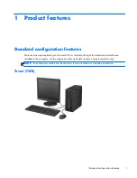
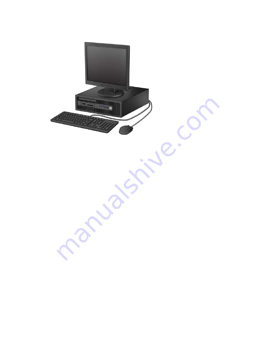
Page 11: ... the model For a complete listing of the hardware and software installed in the computer run the diagnostic utility included on some computer models only NOTE Both computer models can be used in a tower orientation or a desktop orientation Tower TWR Standard configuration features 1 ...

Page 12: ...Small Form Factor SFF 2 Chapter 1 Product features ...

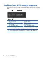
Page 13: ... Dual State Power Button NOTE When a device is plugged into the Microphone Headphone Connector a dialog box will pop up asking if you want to use the connector for a microphone Line In device or a headphone You can reconfigure the connector at any time by double clicking the Audio Manager icon in the Windows taskbar NOTE The Power On Light is normally white when the power is on If it is flashing r...

Page 14: ... optional NOTE When a device is plugged into the Microphone Headphone Connector a dialog box will pop up asking if you want to use the connector for a microphone Line In device or a headphone You can reconfigure the connector at any time by double clicking the Audio Manager icon in the Windows taskbar NOTE The Power On Light is normally white when the power is on If it is flashing red there is a p...

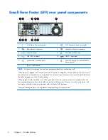
Page 15: ...o the blue Line In Audio Connector a dialog box will pop up asking if you want to use the connector for a line in device or a microphone You can reconfigure the connector at any time by double clicking the Audio Manager icon in the Windows taskbar When a graphics card is installed in one of the system board slots the video connectors on the graphics card and the integrated graphics on the system b...

Page 16: ...ugged into the blue Line In Audio Connector a dialog box will pop up asking if you want to use the connector for a line in device or a microphone You can reconfigure the connector at any time by double clicking the Audio Manager icon in the Windows taskbar When a graphics card is installed in one of the system board slots the video connectors on the graphics card and the integrated graphics on the...

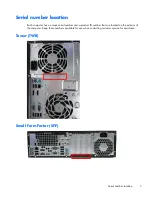
Page 17: ...as a unique serial number and a product ID number that are located on the exterior of the computer Keep these numbers available for use when contacting customer service for assistance Tower TWR Small Form Factor SFF Serial number location 7 ...

Page 18: ...ed airflow Activating the Windows operating system The first time you turn on the computer the operating system is set up and activated automatically This process takes about 5 to 10 minutes Carefully read and follow the instructions on the screen to complete the activation We recommend that you register your computer with HP during operating system setup so you can receive important software upda...

Page 19: ... for the operating system from http www hp com support Select your country and language select Download drivers and software and firmware enter the model number of the computer and press Enter Customizing the monitor display If you wish you can select or change the monitor refresh rates screen resolution color settings font sizes and power management settings For more information refer to the onli...

Page 20: ...test updates during the initial installation and periodically throughout the life of the computer Run Windows Update as soon as possible after you set up your computer 1 Point to the upper right or lower right corner of the Start screen to display the charms 2 Click Settings Change PC Settings Windows Update 3 Run Windows Update monthly thereafter Customizing the monitor display You can customize ...

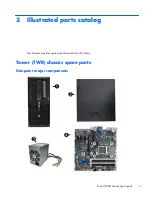
Page 21: ...3 Illustrated parts catalog This chapter provides spare part information for all chassis Tower TWR chassis spare parts Computer major components Tower TWR chassis spare parts 11 ...

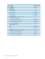
Page 22: ...t Windows 8 696794 001 For use in models with Windows 8 Standard 696794 501 For use in models with Windows 8 Professional 696794 601 For use in models with NetClone 726848 001 Memory modules PC3 12800 8 GB 689375 001 4 GB 671613 001 2 GB 671612 001 Processors include replacement thermal material Intel Core i7 4770 3 4 GHz 8 MB L3 cache 727373 001 Intel Core i5 4670 3 4 GHz 6 MB L3 cache 727381 001...

Page 23: ... 14 inch 1 straight end 1 angled end 732753 001 Hard drive SATA cable 17 7 inch 2 straight ends 639959 001 DMS 59 to dual VGA cable 463023 001 Adapter DisplayPort to VGA 632484 001 Adapter DisplayPort to DVI 662723 001 Adapter DisplayPort to HDMI 617450 001 Adapter DVI to VGA 657401 001 Adapter DVI I to VGA 720216 001 202997 001 DisplayPort cable 487562 001 Tower TWR chassis spare parts 13 ...

Page 24: ...el blank 732770 001 Printer port PCI card 638817 001 HP Ultraslim Keyed Cable Lock 703372 001 Adapter 2 5 inch hard drive 586721 001 Hard drive grommet for use on 2 5 inch drives 594220 001 Hard drive grommet for use on 3 5 inch drives 450712 001 Hard drive carrier 2 5 inch to 3 5 inch 703597 001 Hard drive conversion bracket 397117 001 Serial port PCI card 638815 001 WLAN antennas 583345 001 Mous...

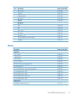
Page 25: ...s Description Spare part number Hard drive 2 TB 7200 rpm 616608 001 1 TB hybrid SSD 724937 001 1 TB 7200 rpm 613202 001 500 GB 7200 rpm 613208 001 500 GB 7200 rpm self encrypting SED 696442 001 500 GB hybrid SSD 724938 001 256 GB Solid state Drive SSD self encrypting SED 680020 001 160 GB Solid state Drive SSD 646809 001 128 GB Solid state Drive SSD 665961 001 128 GB Solid state Drive SSD TCG 7285...

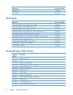
Page 26: ...e GT630 PCIe x16 graphics card 2 GB 702084 001 Intel PRO 1000 single port GbE NIC includes bracket 728562 001 HP WLAN 802 11 a b g n 2x2 PCIe module 695915 001 HP WLAN Bluetooth module 733687 001 Sequential part number listing Spare part number Description 202997 001 Adapter DVI I to VGA 336445 001 Foot kit 397117 001 Hard drive conversion bracket 450712 001 Hard drive grommet for use on 3 5 inch ...

Page 27: ... drive 662723 001 Adapter DisplayPort to DVI 665961 001 128 GB Solid state drive 671612 001 Memory module 2 GB PC3 12800 671613 001 Memory module 4 GB PC3 12800 674315 001 Mouse PS2 optical 674316 001 Mouse USB optical 674317 001 Mouse wireless 674318 001 Mouse USB 680020 001 256 GB Solid state drive self encrypting SED 689375 001 Memory module 8 GB PC3 12800 695915 001 HP WLAN 802 11 a b g n 2x2 ...

Page 28: ...adro NVS315 PCIe x16 graphics card 1 GB 724718 xx1 Keyboard PS 2 for use in models with Windows 8 724720 xx1 Keyboard USB black for use in models with Windows 8 724722 xx1 Keyboard wireless for use in models with Windows 8 724795 001 Mouse washable 724937 001 1 TB hard drive hybrid SSD 724938 001 500 GB hard drive hybrid SSD 726848 001 System board for use in NetClone models 727373 001 Intel Core ...

Page 29: ... assembly 732751 001 Front bezel for use in all countries and regions except for China 732753 001 Optical drive SATA cable 14 inch 1 straight end 1 angled end 732754 001 Drive power cable 732770 001 Optical drive bezel blank 733686 001 Cable clip 733687 001 HP WLAN Bluetooth module Tower TWR chassis spare parts 19 ...

Page 30: ...ent 702455 001 240W 90 efficient 702456 001 240W standard 702457 001 4 System board includes replacement thermal material For use in models without Windows 8 696794 001 For use in models with Windows 8 Standard 696794 501 For use in models with Windows 8 Professional 696794 601 For use in models with NetClone 727722 001 Memory modules PC3 12800 20 Chapter 3 Illustrated parts catalog ...

Page 31: ...1 Front I O assembly 732755 001 2 Power switch assembly 732756 001 3 SATA drive power cable 732759 001 Hard drive SATA cable 14 inch 1 straight end 1 angled end 732753 001 Optical drive SATA cable 19 5 inch 2 straight ends 638813 001 DMS 59 to dual VGA cable 463023 001 Adapter DisplayPort to VGA 632484 001 Adapter DisplayPort to DVI 662723 001 Adapter DisplayPort to HDMI 617450 001 Adapter DVI to ...

Page 32: ...nter port PCI card 638817 001 HP Ultraslim Keyed Cable Lock 703372 001 Rubber foot 583654 001 Chassis stand 688952 001 Serial port PCI card 638815 001 Adapter 2 5 inch hard drive 586721 001 Hard drive grommet for use on 2 5 inch drives 594220 001 Hard drive grommet for use on 3 5 inch drives 450712 001 Hard drive carrier 2 5 inch to 3 5 inch 703597 001 Hard drive conversion bracket 397117 001 WLAN...

Page 33: ...e part number Hard drive 2 TB 7200 rpm 616608 001 1 TB hard drive hybrid SSD 724937 001 1 TB 7200 rpm 613202 001 500 GB 7200 rpm 613208 001 500 GB 7200 rpm self encrypting SED 696442 001 500 GB hard drive hybrid SSD 724938 001 256 GB Solid state Drive SSD self encrypting SED 680020 001 160 GB Solid state Drive SSD 646809 001 128 GB Solid state Drive SSD 665961 001 128 GB Solid state Drive SSD TCG ...

Page 34: ...acket 728562 001 HP WLAN 802 11 a b g n 2x2 PCIe module 695915 001 HP WLAN Bluetooth module 733687 001 Sequential part number listing Spare part number Description 202997 001 Adapter DVI I to VGA 397117 001 Hard drive conversion bracket 463023 001 DMS 59 to dual VGA cable 450712 001 Hard drive grommet for use on 3 5 inch drives 487562 001 DisplayPort cable 583345 001 WLAN antennas 583654 001 Rubbe...

Page 35: ... USB optical 680020 001 256 GB Solid state drive self encrypting SED 688952 001 Chassis stand 689375 001 Memory module 8 GB PC3 12800 695915 001 HP WLAN 802 11 a b g n 2x2 PCIe NIC 696442 001 500 GB 7200 rpm hard drive self encrypting SED 696794 001 System board for use in models without Windows 8 includes replacement thermal material 696794 501 System board for use in models with Windows 8 Standa...

Page 36: ...37 001 1 TB hard drive hybrid SSD 724938 001 500 GB hard drive hybrid SSD 726848 001 System board for use in models with NetClone 727145 001 Fan duct 727149 001 Speaker 727150 001 Fan sink 727373 001 Intel Core i7 4770 processor 3 4 GHz 8 MB L3 cache 727380 001 Intel Core i5 4570 processor 3 2 GHz 6 MB L3 cache 727381 001 Intel Core i5 4670 processor 3 4 GHz 6 MB L3 cache 727722 001 System board f...

Page 37: ...Spare part number Description 732772 001 Solenoid lock 733687 001 HP WLAN Bluetooth module Small Form Factor SFF chassis spare parts 27 ...

Page 38: ...sudden discharge of static electricity from your finger or other conductor can destroy static sensitive devices or microcircuitry Often the spark is neither felt nor heard but damage occurs An electronic device exposed to electrostatic discharge ESD may not appear to be affected at all and can work perfectly throughout a normal cycle The device may function normally for a while but it has been deg...

Page 39: ...a product Preventing electrostatic damage to equipment Many electronic components are sensitive to ESD Circuitry design and structure determine the degree of sensitivity The following packaging and grounding precautions are necessary to prevent damage to electric components and accessories To avoid hand contact transport products in static safe containers such as tubes bags or boxes Protect all el...

Page 40: ... precautions Cover the work surface with approved static dissipative material Provide a wrist strap connected to the work surface and properly grounded tools and equipment Use static dissipative mats foot straps or air ionizers to give added protection Handle electrostatic sensitive components parts and assemblies by the case or PCB laminate Handle them only at static free work areas Turn off powe...

Page 41: ... and above the monitor to permit the required airflow Never restrict the airflow into the computer by blocking any vents or air intakes Do not place the keyboard with the keyboard feet down directly against the front of the desktop unit as this also restricts airflow Occasionally clean the air vents on all vented sides of the computer Lint dust and other foreign matter can block the vents and limi...

Page 42: ... case follow the procedures described below To remove light stains or dirt use plain water with a clean lint free cloth or swab For stronger stains use a mild dishwashing liquid diluted with water Rinse well by wiping it with a cloth or swab dampened with clear water For stubborn stains use isopropyl rubbing alcohol No rinsing is needed as the alcohol will evaporate quickly and not leave a residue...

Page 43: ...or with a towelette designed for cleaning monitors Do not use sprays or aerosols directly on the screen the liquid may seep into the housing and damage a component Never use solvents or flammable liquids on the monitor To clean the monitor body follow the procedures in Cleaning the Computer Case on page 32 Cleaning the mouse Before cleaning the mouse ensure that the power to the computer is turned...

Page 44: ...re flat flexible cables These cables must be handled with care to avoid damage Apply only the tension required to seat or unseat the cables during insertion or removal from the connector Handle cables by the connector whenever possible In all cases avoid bending or twisting the cables and ensure that the cables are routed in such a way that they cannot be caught or snagged by parts being removed o...

Page 45: ... are working on in this guide for instructions on the replacement procedures WARNING This computer contains a lithium battery There is a risk of fire and chemical burn if the battery is handled improperly Do not disassemble crush puncture short external contacts dispose in water or fire or expose it to temperatures higher than 140ºF 60ºC Do not attempt to recharge the battery NOTE Batteries batter...

Page 46: ...etermines that a failure is imminent it generates a fault alert Cable management Always follow good cable management practices when working inside the computer Keep cables away from major heat sources like the heat sink Do not jam cables on top of expansion cards or memory modules Printed circuit cards like these are not designed to take excessive pressure on them Keep cables clear of sliding or m...

Page 47: ...hrough the operating system then turn off any external devices 4 Disconnect the power cord from the power outlet and disconnect any external devices CAUTION Turn off the computer before disconnecting any cables Regardless of the power on state voltage is always present on the system board as long as the system is plugged into an active AC outlet In some systems the cooling fan is on even when the ...

Page 48: ...ss internal components you must remove the access panel 1 Prepare the computer for disassembly Preparation for disassembly on page 37 2 Lift up on the access panel handle 1 then lift the access panel off the computer 2 38 Chapter 5 Removal and replacement procedures Tower TWR ...

Page 49: ...are the computer for disassembly Preparation for disassembly on page 37 2 Remove the access panel Access panel on page 38 3 Remove the security screw from the side of the hard drive bay just behind the front panel 4 Install the security screw through the middle front bezel release tab to secure the front bezel in place Front bezel security 39 ...

Page 50: ...pare the computer for disassembly Preparation for disassembly on page 37 2 Remove the access panel Access panel on page 38 3 Lift up the three tabs on the side of the bezel 1 then rotate the bezel off the chassis 2 40 Chapter 5 Removal and replacement procedures Tower TWR ...

Page 51: ...ccess panel on page 38 2 Remove the front bezel Front bezel on page 40 3 Remove the bezel blank for the appropriate drive To remove a 5 25 inch bezel blank press inward on the retaining tabs that hold the bezel blank in place 1 then pull the bezel blank from the front bezel 2 NOTE After removing the 5 25 inch drive bezel blank and installing a drive you can install an optional bezel trim piece ava...

Page 52: ...drive bezel blank press inward on the retaining tabs that hold the bezel blank in place 1 then pull the bezel blank from the front bezel 2 NOTE After removing the slim optical drive bezel blank and installing a slim optical drive you can install an optional bezel trim piece available from HP that surrounds the front of the slim optical drive 42 Chapter 5 Removal and replacement procedures Tower TW...

Page 53: ...IMMs must be industry standard 240 pin unbuffered non ECC PC3 12800 DDR3 1600 MHz compliant 1 35 volt or 1 5 volt DDR3 DDR3L SDRAM DIMMs The DDR3 SDRAM DIMMs must also support CAS latency 11 DDR3 1600 MHz 11 11 11 timing contain the mandatory JEDEC SPD information In addition the computer supports 512 Mbit 1 Gbit and 2 Gbit non ECC memory technologies single sided and double sided DIMMs DIMMs cons...

Page 54: ...s with one 2 GB DIMM and three 1 GB DIMMs Channel A should be populated with the 2 GB DIMM and one 1 GB DIMM and Channel B should be populated with the other two 1 GB DIMMs With this configuration 4 GB will run as dual channel and 1 GB will run as single channel In any mode the maximum operational speed is determined by the slowest DIMM in the system Installing DIMMs CAUTION You must disconnect th...

Page 55: ...populate the sockets so that the memory capacity is spread as equally as possible between Channel A and Channel B Refer to Populating DIMM sockets on page 43 for more information 4 Push the module down into the socket ensuring that the module is fully inserted and properly seated Make sure the latches are in the closed position 3 5 Repeat steps 3 and 4 to install any additional modules The compute...

Page 56: ... 1000 single port GbE NIC includes bracket 728562 001 The computer has three PCI Express x1 expansion slots and one PCI Express x16 expansion slot NOTE You can install a PCI Express x1 x8 or x16 expansion card in the PCI Express x16 slots For dual graphics card configurations the first primary card must be installed in the PCI Express x16 slot To remove replace or add an expansion card 1 Prepare t...

Page 57: ...ove the expansion slot cover or the existing expansion card NOTE Before removing an installed expansion card disconnect any cables that may be attached to the expansion card a If you are installing an expansion card in a vacant socket remove the appropriate expansion slot cover on the back of the chassis Lift the expansion slot cover from the expansion slot Expansion cards 47 ...

Page 58: ...the card and carefully rock the card back and forth until the connectors pull free from the socket Lift the card straight up to remove it Be sure not to scrape the card against other components 6 Store the removed card in anti static packaging 7 If you are not installing a new expansion card install an expansion slot cover to close the open slot CAUTION After removing an expansion card you must re...

Page 59: ...n the system board NOTE When installing an expansion card press firmly on the card so that the whole connector seats properly in the expansion card slot 9 Close the expansion card retention latch making sure that it snaps firmly into place 10 Connect external cables to the installed card if needed Connect internal cables to the system board if needed Expansion cards 49 ...

Page 60: ...ck Parallel Port 6 Serial Port COMB black Serial Port 7 Hood Lock HLCK black Hood Lock 8 Hood Sensor HSENSE white Hood Sensor 9 DIMM4 Channel A DIMM4 white Memory Module 10 DIMM3 Channel A DIMM3 black Memory Module 11 DIMM2 Channel B DIMM2 white Memory Module 12 DIMM1 Channel B DIMM1 black Memory Module 13 Power SATAPWR0 black SATA Drives 14 Power PWR white System Board 15 USB 3 0 FRONT USB3 0 blu...

Page 61: ... 001 500 GB 7200 rpm 2 5 inch hard drive self encrypting SED 696442 001 500 GB 7200 rpm hard drive 613208 001 500 GB hard drive hybrid SSD 724938 001 256 GB Solid State Drive SSD self encrypting SED 680020 001 160 GB Solid State Drive SSD 646809 001 128 GB Solid State Drive SSD 665961 001 128 GB Solid State Drive SSD TCG 728559 001 120 GB Solid State Drive SSD 661841 001 Card reader 14 in 1 USB 3 ...

Page 62: ...up correctly in the drive cage and lock in place HP has provided extra guide screws four 6 32 silver and blue isolation mounting guide screws and four silver 6 32 standard guide screws installed on the side of the drive bays The 6 32 isolation mounting screws are required for 3 5 inch hard drives installed in the 3 5 inch hard drive bays The 6 32 standard guide screws are required for a USB 3 0 me...

Page 63: ...ds temperature extremes or products that have magnetic fields such as monitors or speakers If a drive must be mailed place the drive in a bubble pack mailer or other protective packaging and label the package Fragile Handle With Care Drive positions 1 5 25 inch half height drive bay 2 Slim optical drive bay 3 3 5 inch drive bay for optional drive such as a media card reader 4 Primary 3 5 inch inte...

Page 64: ...N When removing the cables pull the tab or connector instead of the cable itself to avoid damaging the cable 5 Press down on the green drivelock mechanism 1 and slide the drive from the drive bay 2 Installing a 5 25 inch drive NOTE HP does not offer a 5 25 inch optical drive for this computer model A 5 25 inch optical drive can be purchased through a third party vendor 1 Prepare the computer for d...

Page 65: ...four M3 metric guide screws from the old drive to the new one CAUTION Use only 5 mm long screws as guide screws Longer screws can damage the internal components of the drive 5 Slide the drive into the drive bay making sure to align the guide screws with the guide slots until the drive snaps into place 6 Connect the power cable and data cable to the rear of the optical drive Drives 55 ...

Page 66: ...el before replacing the front bezel Removing a 3 5 inch device CAUTION All removable media should be taken out of a drive before removing the drive from the computer 1 Prepare the computer for disassembly Preparation for disassembly on page 37 2 Remove the access panel Access panel on page 38 3 Remove the front bezel Front bezel on page 40 4 Disconnect the drive cables from the rear of the drive o...

Page 67: ...5 Press the release lever at the rear of the drive away from the drive 1 and slide the drive from the drive bay 2 Drives 57 ...

Page 68: ...ions on page 50 for more information 4 Install 6 32 guide screws in the holes on each side of the drive NOTE HP has supplied four extra 6 32 guide screws on top of the drive cage Refer to Drives on page 51 for an illustration of the extra guide screws location When replacing a drive transfer the four 6 32 guide screws from the old drive to the new one 5 Slide the drive into the drive bay making su...

Page 69: ...en out of a drive before removing the drive from the computer 1 Prepare the computer for disassembly Preparation for disassembly on page 37 2 Remove the access panel Access panel on page 38 3 Remove the front bezel Front bezel on page 40 4 Disconnect the power cable and data cable from the back of the drive CAUTION When removing the cables pull the tab or connector instead of the cable itself to a...

Page 70: ...e used the release latch must be attached a Peel the backing off the adhesive on the release latch b Without allowing the release latch to touch the optical drive carefully align the holes on the release latch with the pins on the side of the optical drive Make sure the release latch is oriented properly c Insert the pin at the front of the optical drive into the hole at the end of the release lat...

Page 71: ...board drive connectors 8 Replace the front bezel NOTE An optional bezel trim piece that surrounds the front of the slim optical drive is available from HP Install the bezel trim piece in the front bezel before replacing the front bezel Removing a 3 5 inch or 2 5 inch hard drive NOTE Before you remove the old hard drive be sure to back up the data from the old hard drive so that you can transfer th...

Page 72: ...4 Release the drive by pulling the release tab away from the drive 1 and sliding the drive out of the bay 2 5 Remove the four guide screws two on each side from the old drive You will need these screws to install a new drive 62 Chapter 5 Removal and replacement procedures Tower TWR ...

Page 73: ...d drives are installed on the exterior of the hard drive bays Extra guide screws for 2 5 inch hard drives are not provided on the chassis but can be purchased from HP Refer to Drives on page 51 for an illustration of the extra 6 32 isolation mounting guide screws location If you are replacing a drive transfer the guides screws from the old drive to the new one If you are installing a 3 5 inch hard...

Page 74: ... the drive into the bay adapter bracket ensuring the connector on the drive is fully inserted into the connector on the adapter bracket Secure the drive to the bay adapter bracket by installing four black M3 adapter bracket screws through the sides of the bracket into the drive 64 Chapter 5 Removal and replacement procedures Tower TWR ...

Page 75: ...blue isolation mounting guide screws in the adapter bracket two on each side of the bracket 4 Slide the drive into the drive bay making sure to align the guide screws with the guide slots until the drive snaps into place Drives 65 ...

Page 76: ...6 If installing a new drive connect the opposite end of the data cable to the appropriate system board connector NOTE You must connect the primary hard drive data cable to the dark blue connector labeled SATA0 to avoid any hard drive performance problems If you are adding a second hard drive connect the data cable to one of the light blue SATA connectors 66 Chapter 5 Removal and replacement proced...

Page 77: ...ezel on page 40 4 Disconnect the three front I O cables from the following system board connectors FRONT USB MEDIA 3 0 FRONT AUD 5 Remove the Torx T15 screw that secures the assembly to the chassis 1 6 Rotate the right side of the assembly outward 2 7 Pull the assembly away from the computer while threading the wires through the hole in the front of the chassis To reinstall the assembly reverse th...

Page 78: ...epare the computer for disassembly Preparation for disassembly on page 37 2 Remove the access panel Access panel on page 38 3 Remove the front bezel Front bezel on page 40 4 Disconnect the cable from the system board connector labeled PB LED 68 Chapter 5 Removal and replacement procedures Tower TWR ...

Page 79: ...age the tab that secures the assembly to the chassis 6 Rotate the assembly downward to remove it from the chassis 7 Pull the assembly away from the chassis while threading the cable through the hole in front of the chassis Power switch LED assembly 69 ...

Page 80: ...ration for disassembly on page 37 2 Remove the access panel Access panel on page 38 3 Loosen the four silver captive Torx T15 screws that secure the heat sink to the system board CAUTION Remove fan sink retaining screws in diagonally opposite pairs as in an X to even the downward forces on the processor The pins on the socket are very fragile and any damage to them may require replacing the system...

Page 81: ...m atop the processor 2 CAUTION Fan sink retaining screws should be tightened in diagonally opposite pairs as in an X to evenly seat the heat sink on the processor This is especially important as the pins on the socket are very fragile and any damage to them may require replacing the system board Fan sink 71 ...

Page 82: ...page 70 4 Rotate the locking lever to its full open position 1 5 Raise and rotate the microprocessor retainer to its fully open position 2 6 Carefully lift the processor from the socket 3 CAUTION Do NOT handle the pins in the processor socket These pins are very fragile and handling them could cause irreparable damage Once pins are damaged it may be necessary to replace the system board The heat s...

Page 83: ...t number Speaker 645330 001 1 Prepare the computer for disassembly Preparation for disassembly on page 37 2 Remove the access panel Access panel on page 38 3 Disconnect the speaker wire from the system board connector labeled SPKR 1 4 From the inside of the chassis remove the Torx T15 screw 2 that secures the speaker to the front of the chassis 5 Rotate the top of the speaker downward 3 and then r...

Page 84: ...cess the internal computer components in any of the following circumstances Power outage Startup failure PC component for example processor or power supply failure Forgotten password NOTE The Smart Cover FailSafe Key is a specialized tool available from HP Be prepared order this key before you need it To obtain a FailSafe Key Contact an authorized HP reseller or service provider Order PN 166527 00...

Page 85: ...move the screws the lock may fall into the computer Hold the lock while removing the screws to avoid damaging the lock or internal components 4 From the inside of the chassis disconnect the cable 1 from the system board connector labeled HLOCK 5 Remove the solenoid lock from the chassis 2 To install the solenoid lock reverse the removal procedure Smart Cover Lock solenoid lock 75 ...

Page 86: ...tall both security screws Plug the connector into the system board connector Insert the cable into the clip on the back of the system board USB port Install the clip if necessary NOTE If both the hood lock and hood sensor are installed make sure the hood sensor cable is under the hood lock cable in the clip 76 Chapter 5 Removal and replacement procedures Tower TWR ...

Page 87: ...n for disassembly on page 37 2 Remove the access panel Access panel on page 38 3 Disconnect the cable from the system board connector labeled HSENSE 1 4 Using a tool remove the sensor from the slot by pushing it into the computer to remove it 2 To install the hood sensor reverse the removal procedure Hood sensor 77 ...

Page 88: ...ve the access panel Access panel on page 38 3 From the outside rear side of the chassis remove the three silver Phillips screws that secure the fan to the chassis 4 From the inside of the chassis disconnect the fan control cable 1 from the system board connector labeled CHFAN2 78 Chapter 5 Removal and replacement procedures Tower TWR ...

Page 89: ...5 Lift the fan out of the chassis 2 To install the fan reverse the removal procedure Be sure to orient the air flow out of the computer Fan 79 ...

Page 90: ...ent 702453 001 Power supply 320W 702454 001 Power supply HV 320W 707906 001 1 Prepare the computer for disassembly Preparation for disassembly on page 37 2 Remove the access panel Access panel on page 38 3 Disconnect the power cables from the following system board connectors PWR PWRCPU PWRCMD 80 Chapter 5 Removal and replacement procedures Tower TWR ...

Page 91: ... on the base pan 5 From the outside rear of the chassis remove the four silver Torx T15 screws that connect the power supply to the chassis 6 Press the tab 1 on the base pan in front of the power supply that holds it in place Power supply 81 ...

Page 92: ...rotate slightly into the computer so the power supply clears the lip on the top of the chassis and then lift the power supply out of the chassis 3 To install the power supply reverse the removal procedure 82 Chapter 5 Removal and replacement procedures Tower TWR ...

Page 93: ...assembly Preparation for disassembly on page 37 2 Remove the access panel Access panel on page 38 3 When replacing the system board make sure the following components are removed from the defective system board and installed on the replacement system board Memory modules Memory on page 43 Expansion cards Expansion cards on page 46 Fan sink Fan sink on page 70 Processor Processor on page 72 4 Disco...

Page 94: ...the system board toward the front of the computer to disengage the I O panel and then lift the system board out of the computer 2 When reinstalling the system board first insert the I O panel back into the slots in the rear of the chassis and then align the board with the chassis screw holes NOTE When replacing the system board you must change the chassis serial number in the BIOS 84 Chapter 5 Rem...

Page 95: ... or USB flash drives from the computer 3 Turn off the computer properly through the operating system then turn off any external devices 4 Disconnect the power cord from the power outlet and disconnect any external devices CAUTION Turn off the computer before disconnecting any cables Regardless of the power on state voltage is always present on the system board as long as the system is plugged into...

Page 96: ...he computer for disassembly Preparation for disassembly on page 85 2 Lift up on the access panel handle 1 then lift the access panel off the computer 2 To install the access panel reverse the removal procedure 86 Chapter 6 Removal and replacement procedures Small Form Factor SFF ...

Page 97: ...9 001 1 Prepare the computer for disassembly Preparation for disassembly on page 85 2 Remove the access panel Access panel on page 86 3 Lift up the three tabs on the side of the bezel 1 then rotate the bezel off the chassis 2 To install the front bezel reverse the removal procedure Front bezel 87 ...

Page 98: ...assembly Preparation for disassembly on page 85 2 If the computer is on a stand remove the computer from the stand 3 Remove the access panel Access panel on page 86 4 Remove the front bezel Front bezel on page 87 5 Remove one of the five silver 6 32 standard screws located on top of the drive cage 88 Chapter 6 Removal and replacement procedures Small Form Factor SFF ...

Page 99: ...6 Install the security screw through the middle front bezel release tab to secure the front bezel in place Front bezel security 89 ...

Page 100: ... and pull the blank off the front bezel 2 To remove a slim optical drive bezel blank press the two retaining tabs that hold the bezel blank in place towards the outer right edge of the bezel 3 and slide the bezel blank back and to the right to remove it 4 4 Replace the front bezel NOTE After removing the slim optical drive bezel blank and installing a slim optical drive you can install an optional...

Page 101: ...IMMs must be industry standard 240 pin unbuffered non ECC PC3 12800 DDR3 1600 MHz compliant 1 35 volt or 1 5 volt DDR3 DDR3L SDRAM DIMMs The DDR3 SDRAM DIMMs must also support CAS latency 11 DDR3 1600 MHz 11 11 11 timing contain the mandatory JEDEC SPD information In addition the computer supports 512 Mbit 1 Gbit and 2 Gbit non ECC memory technologies single sided and double sided DIMMs DIMMs cons...

Page 102: ...ld be populated with the 2 GB DIMM and one 1 GB DIMM and Channel B should be populated with the other two 1 GB DIMMs With this configuration 4 GB will run as dual channel and 1 GB will run as single channel In any mode the maximum operational speed is determined by the slowest DIMM in the system Installing DIMMs CAUTION You must disconnect the power cord and wait approximately 30 seconds for the p...

Page 103: ...populate the sockets so that the memory capacity is spread as equally as possible between Channel A and Channel B Refer to Populating DIMM sockets on page 91 for more information 5 Push the module down into the socket ensuring that the module is fully inserted and properly seated Make sure the latches are in the closed position 3 6 Repeat steps 4 and 5 to install any additional modules The compute...

Page 104: ...6 expansion slot NOTE The PCI Express slots support only low profile cards You can install a PCI Express x1 x4 x8 or x16 expansion card in the PCI Express x16 slot For dual graphics card configurations the first primary card must be installed in the PCI Express x16 slot To remove replace or add an expansion card 1 Prepare the computer for disassembly Preparation for disassembly on page 85 2 If the...

Page 105: ...ve the expansion slot cover or the existing expansion card NOTE Before removing an installed expansion card disconnect any cables that may be attached to the expansion card a If you are installing an expansion card in a vacant socket remove the appropriate expansion slot cover on the back of the chassis Pull the slot cover straight up then away from the inside of the chassis Expansion card 95 ...

Page 106: ...er components c If you are removing a PCI Express x16 card pull the retention arm on the back of the expansion socket away from the card and carefully rock the card back and forth until the connectors pull free from the socket Pull the expansion card straight up from the socket then away from the inside of the chassis to release it from the chassis frame Be sure not to scrape the card against the ...

Page 107: ...ard just above the expansion socket on the system board then move the card toward the rear of the chassis 1 so that the bracket on the card is aligned with the open slot on the rear of the chassis Press the card straight down into the expansion socket on the system board 2 NOTE When installing an expansion card press firmly on the card so that the whole connector seats properly in the expansion ca...

Page 108: ...xpansion Card 3 PCI Express x1 X1PCIEXP1 black Expansion Card 4 PCI Express x16 X16PCIEXP black Expansion Card 5 Parallel Port PAR black Parallel Port 6 Serial Port COMB black Serial Port 7 Hood Lock HLCK black Hood Lock 8 Hood Sensor HSENSE white Hood Sensor 9 DIMM4 Channel A DIMM4 white Memory Module 10 DIMM3 Channel A DIMM3 black Memory Module 11 DIMM2 Channel B DIMM2 white Memory Module 12 DIM...

Page 109: ... Optical drives DVD RW drive 657958 001 DVD ROM drive 608394 001 Blu ray BD RW SuperMulti XL Drive 719157 001 Hard drives 2 TB 7200 rpm hard drive 616608 001 1 TB hard drive hybrid SSD 724937 001 1 TB 7200 rpm hard drive 613202 001 500 GB 7200 rpm hard drive 613208 001 500 GB 7200 rpm hard drive self encrypting SED 696442 001 500 GB hard drive hybrid SSD 724938 001 256 GB Solid State Drive SSD sel...

Page 110: ...t connector routed to the 3 5 inch hard drive bay and the second connector routed to the 2 5 inch hard drive bay You must install guide screws to ensure the drive will line up correctly in the drive cage and lock in place HP has provided four extra 6 32 standard guide screws installed on the top of the drive bay The 6 32 standard guide screws are required for a media card reader or a secondary har...

Page 111: ...rting a drive Avoid exposing a hard drive to liquids temperature extremes or products that have magnetic fields such as monitors or speakers If a drive must be mailed place the drive in a bubble pack mailer or other protective packaging and label the package Fragile Handle With Care Drive positions 1 Slim optical drive bay 2 3 5 inch internal hard drive bay 3 3 5 inch drive bay for optional drives...

Page 112: ...e the front bezel Front bezel on page 87 4 Rotate the drive cage to its upright position 5 Disconnect the drive cables from the rear of the drive or if you are removing a media card reader disconnect the USB cable from the system board as indicated in the following illustration 6 Press inward on the release lever at the rear of the drive 1 and slide the drive out of the rear of the drive bay 2 102...

Page 113: ...bezel blank remove the bezel blank See Bezel blanks on page 90 for more information 4 Install 6 32 guide screws in the holes on each side of the drive NOTE HP has supplied four extra 6 32 guide screws on top of the drive cage Refer to Drives on page 99 for an illustration of the extra guide screws location When replacing a drive transfer the four 6 32 guide screws from the old drive to the new one...

Page 114: ...ct the adapter cable from the media card reader to the USB 2 0 connector on the system board labeled MEDIA NOTE Refer to System board connections on page 98 for an illustration of the system board drive connectors 8 Rotate the drive cage back down to its normal position CAUTION Be careful not to pinch any cables or wires when rotating the drive cage down 104 Chapter 6 Removal and replacement proce...

Page 115: ...the access panel Access panel on page 86 3 Disconnect the power cable 1 and data cable 2 from the rear of the optical drive push the green release latch on the right rear side of the drive toward the center of the drive 3 then slide the drive forward and out of the bay through the front bezel 4 CAUTION When removing the cables pull the tab or connector instead of the cable itself to avoid damaging...

Page 116: ... new optical drive can be used the release latch must be attached a Peel the backing off the adhesive on the release latch b Without allowing the release latch to touch the optical drive carefully align the holes on the release latch with the pins on the side of the optical drive Make sure the release latch is oriented properly c Insert the pin at the front of the optical drive into the hole at th...

Page 117: ...onal bezel trim piece that surrounds the front of the optical drive is available from HP Install the bezel trim piece in the front bezel before installing the front bezel Removing and replacing a 3 5 inch hard drive NOTE Before you remove the old hard drive be sure to back up the data from the old hard drive so that you can transfer the data to the new hard drive 1 Prepare the computer for disasse...

Page 118: ...ver out slide the drive back until it stops then lift the drive up and out of the bay 2 6 To install a hard drive you must transfer the silver and blue isolation mounting guide screws from the old hard drive to the new hard drive 108 Chapter 6 Removal and replacement procedures Small Form Factor SFF ...

Page 119: ...of the hard drive NOTE The data cable for the primary hard drive must be connected to the dark blue connector labeled SATA0 on the system board to avoid any hard drive performance problems 9 Replace the access panel 10 If the computer was on a stand replace the stand 11 Reconnect the power cord and turn on the computer 12 Lock any security devices that were disengaged when the access panel was rem...

Page 120: ... of the hard drive 5 Pull outward on the release lever at the rear of the drive 1 then slide the drive back until it stops and pull it down and out of the drive bay 2 Installing a 2 5 inch hard drive 1 Prepare the computer for disassembly Preparation for disassembly on page 85 2 If the computer is on a stand remove the computer from the stand 3 Remove the access panel Access panel on page 86 110 C...

Page 121: ...e sides of the drive bay Press the drive up into the drive bay then slide it forward until it locks in place 7 Connect the power cable and data cable to the back of the hard drive NOTE If the 2 5 inch hard drive is the primary drive connect the data cable to the dark blue SATA connector labeled SATA0 on the system board If it is a secondary drive connect the data cable to one of the light blue SAT...

Page 122: ...e of the chassis and a release lever inside of the chassis WARNING Voltage is always present on the system board when the computer is plugged into an active AC outlet To avoid possible personal injury and damage to the equipment the power cord should be disconnected from the computer and or the AC outlet before opening the computer 1 Prepare the computer for disassembly Preparation for disassembly...

Page 123: ...5 Release the power supply cables from the cable retaining clip under the drive cage Power supply 113 ...

Page 124: ...elease button at the front of the power supply 1 8 Slide the power supply forward 2 and then lift it out of the chassis 3 To install the power supply reverse the removal procedure CAUTION When installing the power supply cables make sure they are properly positioned in the clip under the drive cage 114 Chapter 6 Removal and replacement procedures Small Form Factor SFF ...

Page 125: ...nk 1 Prepare the computer for disassembly Preparation for disassembly on page 85 2 Remove the access panel Access panel on page 86 3 Rotate the fan duct upward 4 Pull the duct away from the chassis to disengage the clips on the duct from the chassis To install the fan duct reverse the removal procedure Fan duct 115 ...

Page 126: ...stances Power outage Startup failure PC component for example processor or power supply failure Forgotten password NOTE The Smart Cover FailSafe Key is a specialized tool available from HP Be prepared order this key before you need it To obtain a FailSafe Key Contact an authorized HP reseller or service provider Order PN 166527 001 for the wrench style key or PN 166527 002 for the screwdriver bit ...

Page 127: ...d lock from the chassis 2 To install the solenoid lock reverse the removal procedure Refer to the following image for the location of the slots on the back of the chassis in which to install the solenoid lock When installing insert the top tabs into the top slots and then rotate the lock downward Then install the security screw on the outside of the computer Plug the connector into the system boar...

Page 128: ...118 Chapter 6 Removal and replacement procedures Small Form Factor SFF ...

Page 129: ... for disassembly on page 85 2 Remove the access panel Access panel on page 86 3 Disconnect the cable from the system board connector labeled HSENSE 1 4 Using a tool remove the sensor from the slot by pushing it into the computer to remove it 2 To install the hood sensor reverse the removal procedure Hood sensor 119 ...

Page 130: ...Cable routing Use the following image to determine proper cable routing in the Small Form Factor computer 120 Chapter 6 Removal and replacement procedures Small Form Factor SFF ...

Page 131: ...mbly on page 85 2 Remove the access panel Access panel on page 86 3 Remove the front bezel Front bezel on page 87 4 Rotate the drive cage to its upright position 5 Disconnect the cables from the system board as follows Yellow connector labeled FRONT_USB Black connector labeled MEDIA 3 0 Blue connector labeled FRONT AUD Front I O assembly 121 ...

Page 132: ...assembly into the chassis 3 and remove it from the chassis To install the front I O assembly reverse the removal procedure NOTE Be sure to correctly route the cables beneath the drive cage when reinstalling the assembly Proper cable routing prevents damage to the cables and allows the drive cage to close properly See Cable routing on page 120 for proper cable placement 122 Chapter 6 Removal and re...

Page 133: ...mputer for disassembly Preparation for disassembly on page 85 2 Remove the access panel Access panel on page 86 3 Remove the front bezel Front bezel on page 87 4 Rotate the drive cage to its upright position 5 Disconnect the cable from the system board connector labeled PB LED Power switch assembly 123 ...

Page 134: ...is 2 while routing the cable through the hole in the chassis To install the power switch assembly reverse the removal procedure NOTE Be sure to correctly route the cables beneath the drive cage when reinstalling the assembly Proper cable routing prevents damage to the cables and allows the drive cage to close properly See Cable routing on page 120 for proper cable placement 124 Chapter 6 Removal a...

Page 135: ...Remove the access panel Access panel on page 86 3 Remove the front bezel Front bezel on page 87 4 Rotate the drive cage to its upright position 5 Disconnect the speaker wire from the white system board connector labeled SPKR 6 Remove the two Torx screws that secure the speaker to the chassis 7 Lift the speaker from the inside of the chassis to remove it To install the speaker reverse the removal p...

Page 136: ...ss panel on page 86 3 Remove the fan duct Fan duct on page 115 4 Loosen the four captive Torx T15 screws that secure the fan sink to the system board tray CAUTION Remove fan sink retaining screws in diagonally opposite pairs as in an X to even the downward forces on the processor This is especially important as the pins on the socket are very fragile and any damage to them may require replacing th...

Page 137: ... the processor to avoid damage that could require replacing the system board Make sure to replace the fan duct Failure to install the fan duct may cause the computer to overheat Processor Description Spare part number Intel Core i7 processor 4770 3 4 GHz 8 MB L3 cache 86W 727373 001 Intel Core i5 processors 4670 3 4 GHz 6 MB L3 cache 86W 727381 001 4570 3 2 GHz 6 MB L3 cache 86W 727380 001 1 Prepa...

Page 138: ... are damaged it may be necessary to replace the system board The heat sink must be installed within 24 hours of installing the processor to prevent damage to the processor s solder connections NOTE After installing a new processor onto the system board always update the system ROM to ensure that the latest version of the BIOS is being used on the computer The latest system BIOS can be found on the...

Page 139: ...aration for disassembly on page 85 2 Remove the access panel Access panel on page 86 3 When replacing the system board make sure the following components are removed from the defective system board and installed on the replacement system board Memory modules Memory on page 91 Expansion cards Expansion card on page 94 Fan sink Fan sink on page 126 Processor Processor on page 127 4 Remove the fan du...

Page 140: ...so change the chassis serial number in the BIOS CAUTION When reconnecting the cables it is important that they be positioned correctly Changing from desktop to tower configuration The Small Form Factor computer can be used in a tower orientation with an optional tower stand that can be purchased from HP 1 Prepare the computer for disassembly Preparation for disassembly on page 85 130 Chapter 6 Rem...

Page 141: ...mputer in a tower orientation HP recommends the use of the optional tower stand 3 Reconnect the power cord and any external devices then turn on the computer NOTE Ensure at least 10 2 centimeters 4 inches of space on all sides of the computer remains clear and free of obstructions Changing from desktop to tower configuration 131 ...

Page 142: ...r On Self Test POST messages Post Messages Disabled suppresses most POST messages such as memory count product name and other non error text messages If a POST error occurs the error is displayed regardless of the mode selected To manually switch to Post Messages Enabled during POST press any key except F1 through F12 Establish an Ownership Tag the text of which is displayed each time the system i...

Page 143: ...propriate time you must restart the computer and again repeatedly press F10 when the monitor light turns green to access the utility 3 A choice of five headings appears in the Computer Setup Utilities menu File Storage Security Power and Advanced 4 Use the arrow left and right keys to select the appropriate heading Use the arrow up and down keys to select the option you want then press Enter To re...

Page 144: ...and date Flash System ROM Allows you to update the system ROM with a BIOS image file located on removable media Replicated Setup Save to Removable Media Saves system configuration to a formatted USB flash media device Restore from Removable Media Restores system configuration from a USB flash media device Default Setup Save Current Settings as Default Saves the current system configuration setting...

Page 145: ... mode is set to User allows you to specify the parameters logical cylinders heads and sectors per track used by the BIOS to translate disk I O requests from the operating system or an application into terms the hard drive can accept Logical cylinders may not exceed 1024 The number of heads may not exceed 256 The number of sectors per track may not exceed 63 CAUTION Ordinarily the translation mode ...

Page 146: ...access to RAID volumes Use this mode with the RAID device driver loaded in the operating system to take advantage of RAID features AHCI default option Allows operating systems with AHCI device drivers loaded to take advantage of more advanced features of the SATA controller NOTE The RAID AHCI device driver must be installed prior to attempting to boot from a RAID AHCI volume If you attempt to boot...

Page 147: ... on the list may be individually excluded from or included for consideration as a bootable operating system source Specify the order of attached hard drives The first hard drive in the order will have priority in the boot sequence and will be recognized as drive C if any devices are attached NOTE To drag a device to a preferred place press Enter To remove the device from consideration as a bootabl...

Page 148: ...system board Default is disabled CAUTION If you enable the stringent security feature and you forget the setup password or the power on password the computer is inaccessible and can no longer be used If you lose or forget the password the system board must be replaced This scenario is not covered under warranty To prevent the computer from becoming permanently unusable record your configured setup...

Page 149: ... is enabled Network Boot Enables disables the computer s ability to boot from an operating system installed on a network server Feature available on NIC models only the network controller must be either a PCI expansion card or embedded on the system board Default is enabled System IDs Allows you to set Asset tag 18 byte identifier a property identification number assigned by the company to the com...

Page 150: ...hile in MS DOS or Windows Safe Mode NOTE Most operating systems control access to the MBR of the current bootable disk the BIOS cannot prevent changes that may occur while the operating system is running Restores the backup Master Boot Record to the current bootable disk Default is disabled Only appears if all of the following conditions are true MBR security is enabled A backup copy of the MBR ha...

Page 151: ...eatures Embedded Security Device Support Virtualization Technology Virtualization Technology Directed I O Embedded Security Device enable disable Permits activation and deactivation of the Embedded Security Device NOTE To configure the Embedded Security Device a Setup password must be set Reset to Factory Settings Do not reset Reset Resetting to factory defaults will erase all security keys and le...

Page 152: ...sfully entered the hard drive will remain inaccessible until one of the passwords is successfully provided during a subsequent cold boot sequence NOTE This selection will only appear when at least one drive that supports the DriveLock feature is attached to the system Secure Boot Configuration This is a feature of Windows 8 Legacy Support Enable Disable Allows you to turn off all legacy support on...

Page 153: ...d Normal Allows certain operating systems to decrease the processors power consumption when the processor is idle Default is extended Runtime Power Management Enable Disable Allows certain operating systems to reduce processor voltage and frequency when the current software load does not require the full capabilities of the processor Default is enabled Unique Sleep State Blink Rates Enable Disable...

Page 154: ... Sets Active State Power Management ASPM of the bus ASPM lets you set lower power modes that activate when the bus is not being used Options are Disabled LOs L1 LOs and L1 Default is ASPM Disabled Network Controller Sets ASPM of the bus ASPM lets you set lower power modes that activate when the bus is not being used Options are Disabled LOs L1 LOs and L1 Default is ASPM Disabled USB 3 0 Controller...

Page 155: ...nabled Option ROM Prompt enable disable Enabling this feature will cause the system to display a message before loading option ROMs Default is enabled After Power Loss off on previous state Default is Power off Setting this option to Power off causes the computer to remain powered off when power is restored Power on causes the computer to power on automatically as soon as power is restored Previou...

Page 156: ...em Default is Auto which sets memory allocation to 512 MB If you select Force the UMA Frame Buffer Size option displays which lets you set the UMA memory size allocation between 32 MB and 1 GB Internal Speaker does not affect external speakers Default is enabled NIC PXE Option ROM Download PXE iSCSI disabled The BIOS contains an embedded NIC option ROM to allow the unit to boot through the network...

Page 157: ...mation to unconfigure ME Watchdog Timer enable disable Allows you to set amount of time for a operating system and BIOS watchdog alert to be sent if the timers are not deactivated BIOS watchdog is deactivated by BIOS and would indicate that a halt occurred during execution if the alert is sent to the management console An operating system alert is deactivated by the operating system image and woul...

Page 158: ...ry Information guide Before you call for technical support If you are having problems with the computer try the appropriate solutions below to try to isolate the exact problem before calling for technical support Run the HP diagnostic tool Run the hard drive self test in Computer Setup Refer to Computer Setup F10 Utility on page 132 for more information Check the Power LED on the front of the comp...

Page 159: ...rly Be in front of your computer when you call Write down the computer serial number product ID number and monitor serial number before calling Spend time troubleshooting the problem with the service technician Remove any hardware that was recently added to your system Remove any software that was recently installed Restore the system from the Recovery Disc Set that you created or restore the syst...

Page 160: ...stalling a non plug and play expansion board or other option See Solving Hardware Installation Problems on page 171 for instructions Be sure that all the needed device drivers have been installed For example if you are using a printer you need a driver for that model printer Remove all bootable media CD DVD or USB device from the system before turning it on If you have installed an operating syste...

Page 161: ...not respond to keyboard or mouse Cause Solution Computer is in Sleep state To resume from Sleep state press the power button CAUTION When attempting to resume from Sleep state do not hold down the power button for more than four seconds Otherwise the computer will shut down and you will lose any unsaved data System has locked up Restart computer Computer date and time display is incorrect Cause So...

Page 162: ...muted or to increase the volume Cannot remove computer cover or access panel Cause Solution Smart Cover Lock featured on some computers is locked Unlock the Smart Cover Lock using Computer Setup In case of forgotten password power loss or computer malfunction you must manually disable the Smart Cover lock A key to unlock the Smart Cover Lock is not available from HP Keys are typically available fr...

Page 163: ...the Startup tab of the System Configuration Utility clear applications that you do not want to launch automatically and the click OK In Windows 8 a On the Start screen right click and then select the All apps icon b Under Windows System click Run c Type msconfig and then press Enter d On the Startup tab of the System Configuration Utility clear applications that you do not want to launch automatic...

Page 164: ...and hold the power button for less than 4 seconds If the hard drive LED turns white then 1 If equipped with a voltage selector check that the voltage selector located on the rear of the power supply is set to the appropriate voltage Proper voltage setting depends on your region 2 Remove the expansion cards one at a time until the 5V_aux light on the system board turns on 3 Replace the system board...

Page 165: ... and the Power LED flashes Red two times once every second followed by a two second pause and the computer beeps two times Beeps stop after fifth iteration but LEDs continue flashing Cause Solution Processor thermal protection activated A fan may be blocked or not turning OR The heat sink is not properly attached to the processor 1 Ensure that the computer air vents are not blocked and the process...

Page 166: ...then power off and replace one device at a time and repeat this procedure until failure occurs Replace the device that is causing the failure Continue adding devices one at a time to ensure all devices are functioning properly 4 Replace the power supply 5 Replace the system board Solving hard drive problems Hard drive error occurs Cause Solution Hard disk has bad sectors or has failed 1 In Windows...

Page 167: ...are problem If this is a newly installed drive run the Computer Setup utility and try adding a POST delay under Advanced Power On Options The device is attached to a SATA port that has been hidden in Computer Setup Run the Computer Setup utility and ensure Device Available is selected for the device s SATA port in Security Device Security Drive responds slowly immediately after power up Run Comput...

Page 168: ...s not correct Run the Computer Setup utility and change boot sequence in Storage Boot Order Hard Drive s Emulation Type is set to None some models Run the Computer Setup utility and change the Emulation Type to Hard Disk in the device s details under Storage Device Configuration Hard drive is damaged Observe if the front panel Power LED is blinking RED and if any beeps are heard See Appendix A POS...

Page 169: ...k tab located on the bottom of the Memory Stick PRO card is not in the locked position Can not write to the media card Cause Solution The media card is a read only memory ROM card Check the manufacturer s documentation included with your card to see if it writable Refer to the previous section for a list of compatible cards Media card is locked Locking the media card is a safety feature that preve...

Page 170: ...tem can recognize the reader and the available ports and then recognize the media inserted in the reader After inserting a media card in the reader the computer attempts to boot from the media card Cause Solution The inserted media card has boot capability 1 If you do not want to boot from the media card remove it during boot or do not select the option to boot from the inserted media card during ...

Page 171: ...the computer Monitor settings in the computer are not compatible with the monitor 1 In Control Panel select Category from the View by list then under Appearance and Personalization select Adjust screen resolution To access Control Panel in Windows 7 click Start and then select Control Panel To access Control Panel in Windows 8 from the Start screen type c and then select Control Panel from the lis...

Page 172: ...deo Replace the system board Monitor does not function properly when used with energy saver features Cause Solution Monitor without energy saver capabilities is being used with energy saver features enabled Disable monitor energy saver feature Dim characters Cause Solution The brightness and contrast controls are not set properly Adjust the monitor brightness and contrast controls Cables are not p...

Page 173: ...he monitor Monitor needs to be degaussed Degauss the monitor Refer to the documentation that came with the monitor for instructions Image is not centered Cause Solution Position may need adjustment Press the monitor s Menu button to access the OSD menu Select ImageControl Horizontal Position or Vertical Position to adjust the horizontal or vertical position of the image No Connection Check Signal ...

Page 174: ...ghts When your computer is in safe mode Safe Mode displays in the corners of your monitor To exit safe mode restart your computer and let Windows start normally To enter Safe Mode in Windows 8 1 Press the Windows logo l to open the Settings charm 2 Select Change PC Settings select General and then under Advanced startup click Restart now 3 Select Troubleshoot select Advanced options select Startup...

Page 175: ...ist you with the synchronization go to the following Web site select the appropriate monitor and download either SP32347 or SP32202 http www hp com support Graphics card is not seated properly or is bad some models 1 Reseat the graphics card 2 Replace the graphics card Certain typed symbols do not appear correct Cause Solution The font you are using does not support that particular symbol Use the ...

Page 176: ...hat the device is connected to the correct jack on the computer The rear audio jack output is the green receptacle The speakers should be plugged into the line out jack and the headphones should be plugged into the headphone jack External speakers plugged into the wrong audio jack on a recently installed sound card See the sound card documentation for proper speaker connection The rear audio jack ...

Page 177: ...be set to use a different audio device as the default output device than what is expected Set the operating system to use the correct audio device Sound from headphones is not clear or muffled Cause Solution Headphones are plugged into the rear audio output connector The rear audio output connector is for powered audio devices and is not designed for headphone use Plug the headphones into the head...

Page 178: ...device than what is expected Set the operating system to use the correct audio device Solving printer problems If you encounter printer problems see the documentation that came with the printer and to the common causes and solutions listed in the following table Printer will not print Cause Solution Printer is not turned on and online Turn the printer on and make sure it is online The correct prin...

Page 179: ...and solutions listed in the following table A wireless keyboard mouse is not working correctly Symptoms include lagging mouse movement jumpy mouse keyboard or no function of mouse keyboard and external drive Cause Solution If your computer is equipped with USB 3 0 ports connected USB 3 0 devices can interfere with the wireless keyboard USB receiver Connect the wireless keyboard USB receiver to a U...

Page 180: ...ot respond to movement or is too slow Cause Solution Mouse connector is not properly plugged into the back of the computer Shut down the computer using the keyboard Windows 7 1 Press the Ctrl and Esc keys at the same time or press the Windows logo key to display the Start menu 2 Use the arrow keys to select Shut Down and then press Enter 3 After the shutdown is complete plug the mouse connector in...

Page 181: ...e computer If you install a non plug and play device you must reconfigure the computer after completing installation of the new hardware In Windows use the Add Hardware Wizard and follow the instructions that appear on the screen To open the Add Hardware Wizard open a Command Prompt and open hdwwiz exe WARNING When the computer is plugged into an AC power source voltage is always applied to the sy...

Page 182: ...Device Manager in Windows 8 from the Start screen type c select Control Panel from the list of applications and then select Device Manager USB ports on the computer are disabled in Computer Setup Run the Computer Setup utility and ensure that Device available is selected for appropriate USB ports under Security USB Security Computer will not start Cause Solution Wrong memory modules were used in t...

Page 183: ...mes once every second followed by a two second pause and the computer beeps six times Beeps stop after fifth iteration but LEDs continue flashing Cause Solution Graphics card some models is not seated properly or is bad or system board is bad For systems with a graphics card 1 Reseat the graphics card Power on the system 2 Replace the graphics card 3 Replace the system board For systems with integ...

Page 184: ...ions S5 Wake on LAN Wake on LAN is not enabled To enable Wake on LAN in Windows 7 1 Select Start Control Panel Network and Sharing Center 2 Under Tasks select Manage network connections 3 Click Local Area Connection 4 Click the Properties button 5 Click the Configure button 6 Click the Power Management tab then select Allow this device to wake the computer To enable Wake on LAN in Windows 8 1 From...

Page 185: ...k controller is not set up properly Check for the device status within Windows such as Device Manager for driver load and the Network Connections applet within Windows for link status To access Device Manager in Windows 7 click Start select Control Panel and then select Device Manager To access Device Manager in Windows 8 from the Start screen type c select Control Panel from the list of applicati...

Page 186: ...ers are loaded and that the driver parameters match the configuration of the network controller Make sure the correct network client and protocol is installed The network controller is not configured for this computer Select the Network and Sharing Center icon in the Control Panel and configure the network controller To access Control Panel in Windows 7 click Start and then select Control Panel To...

Page 187: ...ce Cannot connect to network server when attempting Remote System Installation Cause Solution The network controller is not configured properly Verify Network Connectivity that a DHCP Server is present and that the Remote System Installation Server contains the NIC drivers for your NIC System setup utility reports unprogrammed EEPROM Cause Solution Unprogrammed EEPROM Contact an authorized service...

Page 188: ...dule is not seated properly Replace module with the correct industry standard device for the computer On some models ECC and non ECC memory modules cannot be mixed Out of memory error Cause Solution You have run out of memory to run the application Check the application documentation to determine the memory requirements Memory count during POST is wrong Cause Solution The memory modules may not be...

Page 189: ... hot 1 Make sure the airflow to the computer is not blocked 2 Make sure the fans are connected and working properly some fans only operate when needed 3 Make sure the processor heat sink is installed properly Power LED flashes Red three times once every second followed by a two second pause Cause Solution Processor is not seated properly or not installed 1 Check to see that the processor is presen...

Page 190: ...und identified Cause Solution Cable could be loose Check cable connections The system may not have automatically recognized a newly installed device See reconfiguration directions in the Solving Hardware Installation Problems on page 171 section If the system still does not recognize the new device check to see if the device is listed within Computer Setup If it is listed the probable cause is a d...

Page 191: ...fferent media to confirm whether media is valid Media has been inserted upside down Re insert the media with the label facing up The DVD ROM drive takes longer to start because it has to determine the type of media played such as audio or video Wait at least 30 seconds to let the DVD ROM drive determine the type of media being played If the disc still does not start read the other solutions listed...

Page 192: ... USB port that has been hidden in Computer Setup Run the Computer Setup utility and enable USB ports in Security USB Security The device was not properly seated before power up Ensure the device is fully inserted into the USB port before applying power to the system System will not boot from USB flash drive Cause Solution Boot order is not correct Run the Computer Setup utility and change boot seq...

Page 193: ...ter USB ports on the computer are disabled in Computer Setup Run the Computer Setup utility and ensure that the USB ports are set to Enabled in Security USB Security Solving Internet access problems If you encounter Internet access problems consult your Internet Service Provider ISP or refer to the common causes and solutions listed in the following table Unable to connect to the Internet Cause So...

Page 194: ...formation that the Web server can later retrieve Windows 7 1 Select Start Control Panel 2 Click Internet Options 3 In the Browsing history section on the General tab click the Delete button 4 Select the Cookies check box and click the Delete button Windows 8 1 From the Start screen type c and then select Control Panel from the list of applications 2 Click Internet Options 3 In the Browsing history...

Page 195: ...ting system other than the factory installed operating system check to be sure it is supported on the system If you encounter software problems see the applicable solutions listed in the following table Computer will not continue and the HP logo does not display Cause Solution ROM issue POST error has occurred Observe the beeps and LED lights on the front of the computer See Appendix A POST error ...

Page 196: ... use Automatic Repair to fix problems that might prevent Windows from starting correctly To access Automatic Repair 1 Press the Windows logo l to open the Settings charm 2 Select Change PC Settings select General and then under Advanced startup click Restart now 3 Select Troubleshoot select Advanced options and then select Automatic Repair Windows starts Automatic Repair 4 Select the account to us...

Page 197: ...Enabled mode during POST press any key except F10 F11 or F12 The default mode is POST Message Disabled The speed at which the computer loads the operating system and the extent to which it is tested are determined by the POST mode selection Quick Boot is a fast startup process that does not run all of the system level tests such as the memory test Full Boot runs all of the ROM based system tests a...

Page 198: ... on page 200 2 Remove expansion boards 3 Replace the system board 110 Out of Memory Space for Option ROMs Recently added PCI expansion card contains an option ROM too large to download during POST 1 If a PCI expansion card was recently added remove it to see if the problem remains 2 In Computer Setup set Advanced Device Options NIC PXE Option ROM Download to DISABLE to prevent PXE option ROM for t...

Page 199: ...d test using HP only memory 4 Verify proper memory module type 201 Memory Error RAM failure 1 Ensure memory modules are correctly installed 2 Verify proper memory module type 3 Remove and replace the identified faulty memory module s 4 If the error persists after replacing memory modules replace the system board 213 Incompatible Memory Module in Memory Socket s X X A memory module in memory socket...

Page 200: ...CMOS See Appendix B Password security and resetting CMOS on page 200 3 Verify monitor is attached and turned on 4 Replace the graphics card if possible 510 Flash Screen Image Corrupted Flash Screen image has errors Reflash the system ROM with the latest BIOS image 511 CPU CPUA or CPUB Fan not Detected CPU fan is not connected or may have malfunctioned 1 Reseat CPU fan 2 Reseat fan cable 3 Replace ...

Page 201: ...y cache is not working properly and will be disabled Replace system board if minimal graphics degrading is an issue 912 Computer Cover Has Been Removed Since Last System Startup Computer cover was removed since last system startup No action required 917 Front Audio Not Connected Front audio harness has been detached or unseated from motherboard Reconnect or replace front audio harness 918 Front US...

Page 202: ...plicable Available at http www hp com support 3 Back up contents and replace hard drive 1796 SATA Cabling Error One or more SATA devices are improperly attached For optimal performance the SATA 0 and SATA 1 connectors must be used before SATA 2 and SATA 3 Ensure SATA connectors are used in ascending order For one device use SATA 0 For two devices use SATA 0 and SATA 1 For three devices use SATA 0 ...

Page 203: ...e power cord restore the original memory configuration and reboot the computer 4 If the error persists replace the system board 2202 PMM Deallocation Error during MEBx cleanup Memory error during POST execution of the Management Engine ME BIOS Extensions option ROM 1 Reboot the computer 2 Unplug the power cord re seat the memory modules and reboot the computer 3 If the memory configuration was rec...

Page 204: ...on and ME firmware version 3 If the error still persists replace the system board 2217 ME Firmware Version request failure ME firmware is not properly responding to BIOS query for version information 1 Reboot the computer 2 If the error persists update to the latest BIOS version and ME firmware version 3 If the error still persists replace the system board 2218 ME Firmware Version should be update...

Page 205: ...grouping 1 Reboot the computer 2 If the error persists update to the latest BIOS version and ME firmware version 3 If the error still persists replace the system board 2233 HECI error during MEBx execution Error occurred during MEBx execution which fails into MEI or HECI grouping 1 Reboot the computer 2 If the error persists update to the latest BIOS version and ME firmware version 3 If the error ...

Page 206: ...ltage is always applied to the system board To reduce the risk of personal injury from electrical shock and or hot surfaces be sure to disconnect the power cord from the wall outlet and allow the internal system components to cool before touching NOTE If you see flashing LEDs on a PS 2 keyboard look for flashing LEDs on the front panel of the computer and refer to the following table to determine ...

Page 207: ...cond followed by a two second pause Beeps stop after fifth iteration but LEDs continue until problem is solved 4 Power failure power supply is overloaded 1 Open the hood and ensure the 4 or 6 wire power supply cable is seated into the connector on the system board 2 Check if a device is causing the problem by removing ALL attached devices such as hard diskette or optical drives and expansion cards...

Page 208: ...sum 1 Reflash the system ROM with the latest BIOS image 2 Replace the system board Red Power LED flashes nine times once every second followed by a two second pause Beeps stop after fifth iteration but LEDs continue until problem is solved 9 System powers on but is unable to boot 1 Check that the voltage selector located on the rear of the power supply some models is set to the appropriate voltage...

Page 209: ... the power supply is set to the appropriate voltage Proper voltage setting depends on your region 2 Replace the system board OR Press and hold the power button for less than 4 seconds If the hard drive LED does not turn on white then 1 Check that the unit is plugged into a working AC outlet 2 Open hood and check that the power button harness is properly connected to the system board 3 Check that b...

Page 210: ...h passwords only the setup password will give you access to Computer Setup When both passwords are set the setup password can also be used in place of the power on password as an override to log in to the computer This is a useful feature for a network administrator If you forget the password for the computer you can clear that password so you can gain access to the information on the computer by ...

Page 211: ...uce the risk of personal injury from electrical shock and or hot surfaces be sure to disconnect the power cord from the wall outlet and allow the internal system components to cool before touching CAUTION When the computer is plugged in the power supply always has voltage applied to the system board even when the unit is turned off Failure to disconnect the power cord can result in damage to the s...

Page 212: ...xternal equipment connected to the computer WARNING To reduce the risk of personal injury from electrical shock and or hot surfaces be sure to disconnect the power cord from the wall outlet and allow the internal system components to cool before touching CAUTION When the computer is plugged in the power supply always has voltage applied to the system board even when the unit is turned off Failure ...

Page 213: ...e the Illustrated Parts Service Map IPSM 5 Replace the computer cover or access panel 6 Reconnect the external devices 7 Plug in the computer and turn on power NOTE You will receive POST error messages after clearing CMOS and rebooting advising you that configuration changes have occurred Use Computer Setup to reset any special system setups along with the date and time For instructions on Compute...

Page 214: ...aced Isolate true hardware failures The diagnostics run outside of the operating system so they effectively isolate hardware failures from issues that may be caused by the operating system or other software components Failure ID When a failure is detected that requires hardware replacement a 24 digit Failure ID is generated This ID can then be provided to the call agent who will either schedule su...

Page 215: ...1 Go to http www hp com 2 Click the Support Drivers link 3 Select the Drivers Software tab 4 Enter the product name in the text box and click Search 5 Select your specific computer model 6 Select your operating system 7 In the Diagnostic section click the HP UEFI Support Environment link This link provides additional information or Click the Download button and select Run The download includes ins...

Page 216: ... working state or even back to the original factory state all with simple steps This section provides information about the following processes Creating recovery media and backups Restoring and recovering your system NOTE This section describes an overview of backing up restoring and recovering options For more details about the tools provided see Help and Support From the Start screen type h and ...

Page 217: ...ic time A system restore point contains information that Windows uses such as registry settings Windows creates a system restore point for you automatically during a Windows update and during other system maintenance such as a software update security scanning or system diagnostics You can also manually create a system restore point at any time For more information and steps for creating specific ...

Page 218: ...e backing up data to another drive See Using Windows 8 Refresh on page 208 If you want to reset your computer to its original state Windows Reset provides an easy way to remove all personal data apps and settings and reinstall Windows The Reset recovery tool reinstalls the operating system and HP programs and drivers that were installed at the factory Software not installed at the factory must be ...

Page 219: ...he Windows 8 operating system media and the Driver Recovery media purchased separately see Recovery using Windows 8 operating system media purchased separately on page 211 3 If the HP Recovery partition is listed restart the computer and then press esc while the company logo is displayed The computer Startup Menu displays 4 Press f11 to select the System Recovery option 5 Choose your keyboard layo...

Page 220: ...start the computer and then press esc while the company logo is displayed The computer Startup Menu displays 4 Press f11 to select the System Recovery option 5 Choose your keyboard layout 6 Select Troubleshoot 7 Select Reset 8 Follow the on screen instructions to continue Recovery using the Windows 8 recovery USB flash drive To recover your system using the recovery USB flash drive you previously ...

Page 221: ...nstalled on the computer are permanently removed When reformatting is complete the recovery process helps you restore the operating system as well as drivers software and utilities To initiate recovery using Windows 8 operating system media NOTE This process takes several minutes 1 If possible back up all personal files 2 Restart the computer and then follow the instructions provided with the Wind...

Page 222: ...saved by Windows System Restore at a specific time A system restore point contains information that Windows uses such as registry settings Windows creates a system restore point for you automatically during a Windows update and during other system maintenance such as a software update security scanning or system diagnostics You can also manually create a system restore point at any time For more i...

Page 223: ...try again The number of discs in the recovery disc set depends on your computer model typically 3 to 6 DVDs The Recovery Media Creation program tells you the specific number of blank discs needed to make the set If you are using a USB flash drive the program will tell you the size of the drive required to store all the data minimum of 8 GB NOTE The process of creating recovery media is lengthy You...

Page 224: ... create recovery discs using HP Recovery Disc Creator The recovery discs allows you to reinstall your original operating system as well as select drivers and applications if the hard drive becomes corrupted HP Recovery Disc Creator creates two kinds of recovery discs Windows 7 operating system DVD Installs the operating system without additional drivers or applications Driver Recovery DVD Installs...

Page 225: ... a screen shot of your settings The screen shot can be a time saver if you have to reset your preferences When backing up to discs number each disc after removing it from the drive NOTE For detailed instructions on various backup and restore options perform a search for these topics in Help and Support To access Help and Support select Start Help and Support NOTE Windows includes the User Account ...

Page 226: ...ooklet included with the computer NOTE Always use the System Restore procedure before you use the System Recovery program See System Restore on page 215 You must choose one of the following methods to perform a System Recovery Recovery image Run System Recovery from a recovery image stored on your hard disk drive The recovery image is a file that contains a copy of the original factory shipped sof...

Page 227: ...ces and then turn the computer back on System Recovery when Windows is not responding CAUTION System Recovery deletes all data and programs you created or installed If Windows is not responding but the computer is working follow these steps to perform a System Recovery 1 Turn off the computer If necessary press and hold the power button until the computer turns off 2 Disconnect all peripheral devi...

Page 228: ...done so select Back up your files first recommended and then click Next Otherwise select Recover without backing up your files and then click Next 8 If you are prompted to insert the next recovery disc do so 9 When Recovery Manager is finished remove the recovery disc or the recovery USB flash drive from the system 10 Click Finish to restart the computer Using HP Recovery Disc operating system dis...

Page 229: ...drive before the Windows operating system loads NOTE If the computer does not boot to the DVD restart the computer and press Esc as the computer is powering on to see the startup menu Use the arrow keys to select the boot menu and press Enter Use the arrow keys to select the location where the recovery DVD is inserted Press Enter to boot from that device 3 When prompted press any keyboard key 4 Fo...

Page 230: ...nt Before beginning these procedures ensure that you are discharged of static electricity by briefly touching a grounded metal object NOTE The lifetime of the lithium battery can be extended by plugging the computer into a live AC wall socket The lithium battery is only used when the computer is NOT connected to AC power HP encourages customers to recycle used electronic hardware HP original print...

Page 231: ...ery into position positive side up The battery holder automatically secures the battery in the proper position Type 2 a To release the battery from its holder squeeze the metal clamp that extends above one edge of the battery When the battery pops up lift it out 1 b To insert the new battery slide one edge of the replacement battery under the holder s lip with the positive side up Push the other e...

Page 232: ...eps to complete this procedure 8 Replace the access panel 9 Plug in the computer and turn on power to the computer 10 Reset the date and time your passwords and any special system setups using Computer Setup 11 Lock any security devices that were disengaged when the access panel was removed 222 Appendix A Battery replacement ...

Page 233: ...ilSafe Key to open the computer cover You will need the key to access the internal computer components in any of the following circumstances Power outage Startup failure PC component for example processor or power supply failure Forgotten password NOTE The Smart Cover FailSafe Key is a specialized tool available from HP Be prepared order this key before you need it To obtain a FailSafe Key Contact...

Page 234: ...ff any external devices 4 Disconnect the power cord from the power outlet and disconnect any external devices CAUTION Regardless of the power on state voltage is always present on the system board as long as the system is plugged into an active AC outlet You must disconnect the power cord to avoid damage to the internal components of the computer 5 Use the Smart Cover FailSafe Key to remove the ta...

Page 235: ...or Removing the Smart Cover Lock Screw from the Ultra slim Desktop 6 You can now remove the access panel To reattach the Smart Cover Lock secure the lock in place with the tamper proof screws Using the smart cover FailSafe key to remove the smart cover lock 225 ...

Page 236: ...cy responsible for evaluation in the country where the power cord set will be installed 2 The power cord set must have a minimum current capacity of 10A 7A Japan only and a nominal voltage rating of 125 or 250 volts AC as required by each country s power system 3 The diameter of the wire must be a minimum of 0 75 mm2 or 18AWG and the length of the cord must be between 1 8 m 6 feet and 3 6 m 12 fee...

Page 237: ... set fittings appliance coupler and wall plug must bear the certification mark of the agency responsible for evaluation in the country where it will be used 2 The flexible cord must be Type SVT or equivalent No 18 AWG 3 conductor The wall plug must be a two pole grounding type with a NEMA 5 15P 15A 125V or NEMA 6 15P 15A 250V configuration 3 Appliance coupler flexible cord and wall plug must bear ...

Page 238: ...is 10 C Hr The upper limit may be limited by the type and number of options installed Relative Humidity noncondensing Operating Nonoperating 38 7 C max wet bulb 10 90 5 95 10 90 5 95 Maximum Altitude unpressurized Operating Nonoperating 10 000 ft 30 000 ft 3048 m 9144 m Power Supply Operating Voltage Range Rated Voltage Range1 Rated Line Frequency Operating Line Frequency 90 264 VAC 100 240 VAC 50...

Page 239: ...Operating Nonoperating 50 to 95 F 22 to 140 F 10 to 35 C 30 to 60 C NOTE Operating temperature is derated 1 0 C per 300 m 1000 ft to 3000 m 10 000 ft above sea level no direct sustained sunlight Maximum rate of change is 10 C Hr The upper limit may be limited by the type and number of options installed Relative Humidity noncondensing Operating Nonoperating 38 7 C max wet bulb 10 90 5 95 10 90 5 95...

Page 240: ...ted power supply This allows the system to pass the CE mark requirements for use in the countries of the European Union The active power factor corrected power supply also has the added benefit of not requiring an input voltage range select switch 230 Appendix D Specifications ...

Page 241: ...ctrostatic discharge 28 keyboard cleaning 33 keyboard keys 33 CD ROM or DVD problems 180 chasis types illustrated 28 chassis fan TWR spare part number 17 chassis stand spare part number 22 cleaning computer 32 mouse 33 safety precautions 32 CMOS backing up 200 clearing and resetting 202 computer specifications 229 computer cleaning 32 country power cord set requirements 227 Customer Support 148 D ...

Page 242: ...15 23 hard drive 2 5 inch SFF installation 110 SFF removal 110 TWR installation 63 TWR removal 61 hard drive 3 5 inch SFF installation 107 SFF removal 107 TWR installation 63 TWR removal 61 hard drive problems 156 hard drive recovery Windows 7 216 Windows 8 208 hardware installation problems 171 Help and Support Windows 7 212 helpful hints 149 hood sensor SFF spare part number 119 spare part numbe...

Page 243: ...8 problems audio 166 CD ROM or DVD 180 flash drive 182 front panel 183 general 151 hard drive 156 hardware installation 171 Internet access 183 keyboard 169 Media Card Reader 159 memory 177 monitor 160 mouse 169 network 174 power 155 printer 168 processor 179 software 185 processor SFF removal and replacement 127 spare part number 12 18 21 26 TWR removal and replacement 72 processor problems 179 p...

Page 244: ...ont bezel spare part number 20 26 front I O assembly removal and replacement 121 front I O assembly spare part number 21 power supply removal and replacement 112 power supply spare part number 20 25 power switch assembly removal and replacement 123 power switch assembly spare part number 21 26 preparation for disassembly 85 processor removal and replacement 127 SATA cable spare part number 21 Smar...

Page 245: ...sembly 37 processor removal and replacement 72 SATA hard drive cable spare part number 17 SATA optical drive cable spare part number 17 solenoid lock removal and replacement 74 77 speaker removal and replacement 73 speaker spare part number 14 17 system board removal and replacement 83 system board spare part number 12 17 U unlocking access panel 223 V ventilation proper 31 W Wake on LAN feature 1...

Reviews: