HP ProCurve MSM765zl Installation Manual Download Page 10

3 Initially connecting and configuring

This chapter describes how to connect to the switch, activate a controller, configure the switch for
the controller, and then perform initial controller configuration. Finally, information on restarting
and resetting the controller is provided.

Connect to the switch

Although full information on the switch command line interface (CLI) is provided in the switch
documentation, the basic switch CLI commands needed to work with the controller are provided
in this document.

NOTE:

Although not described in this document, it is also possible to perform switch configuration

via a telnet session with an Ethernet connection to the switch.

1.

Using a null-modem (crossover) serial cable, connect a computer to the serial port of the switch
Management Module.

2.

On the computer, configure a serial terminal program in VT100 mode, with baud rate 9600,
8 data bits, no parity, 1 stop bit, and no flow control.

3.

Open a terminal session with the switch and press

Enter

several times until the welcome screen

appears. (A different screen may appear if another session was already open.)
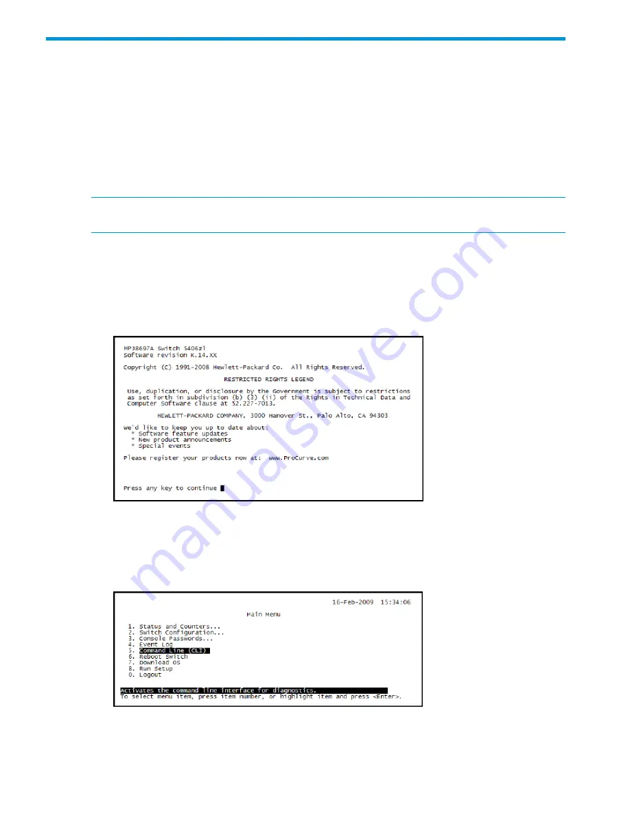
4.

Press any key to continue. The switch CLI prompt appears. It looks similar to this:

HP Switch 5406zl#

5.

If instead, the switch menu is shown, return to the top-level menu and then exit to the CLI by
selecting

Command Line (CLI)

on the

Main Menu

.

The switch CLI prompt appears, similar to this.

HP Switch 5406zl#

10

Initially connecting and configuring

Summary of Contents for ProCurve MSM765zl

Page 1: ...is document describes how to install and initially configure the MSM765 zl Premium Mobility Controller J9370A This product is hereafter referred to as controller See also the MSM Controllers Configuration Guide HP Part Number 5998 7937 Published June 2015 Edition 1 ...

Page 2: ...tional warranty HP shall not be liable for technical or editorial errors or omissions contained herein Links to third party websites take you outside the HP website HP has no control over and is not responsible for information outside HP com Acknowledgments Microsoft and Windows are trademarks of the Microsoft group of companies Mozilla and Firefox are trademarks of the Mozilla Foundation Warranty...

Page 3: ... Connect to the switch 10 Activate the controller 11 Install the product license key 12 Configure the switch for the controller 12 Initial controller configuration 15 Restarting and resetting the controller 18 4 Support and other resources 20 Online documentation 20 Contacting HP 20 HP websites 20 Typographic conventions 20 A Replacing hardware components 21 Replacing or removing a controller 21 R...

Page 4: ...n the controller is booted to Service OS Flashing green Module Status green orange Controller is operational On green Error condition Flashing on orange This LED is off by default Flashing cycle green or orange is 400ms on 400ms off At boot the Module Status HDD Status and CF Status LEDs are green for 2s then orange for 2s then back to green for 1s and finally all are turned off On during boot onl...

Page 5: ...y on either port Off Switch LEDs The following figures show the Test Fault and Module Status LEDs on the switches in which the controller can be installed Figure 2 Test Fault and Module Status LEDs on a Series 5400 zl switch 1 2 3 1 Fault LED 2 Test LED 3 Module Status LEDs Figure 3 Test Fault and Module Status LEDs on a Series 8212 zl switch 1 2 3 1 Fault LED 2 Test LED 3 Module Status LEDs Seria...

Page 6: ...rial number is found on its bottom Figure 4 Locating the disk drive serial number 1 1 Disk drive serial and product numbers SN SGxxxxxxxx The serial number for the controller is located on the back left corner of the controller The serial number of the controller can also be found in the management tool or through the CLI Figure 5 Locating the controller serial number 1 1 Controller serial number ...

Page 7: ... at a time when the switch is powered on Respect the temperature specifications for the controller When installing the controller into a switch the switch can be powered on or off The installation procedure in this guide assumes the switch is powered on Environmental specifications Non Operating 10 C to 65 C 14 F to 149 F Operating 0 C to 40 C 32 F to 104 F 1 2 Temperature 15 to 90 at 65 C 149 F 1...

Page 8: ...e screws in the cover plate over the slot where the controller is to be installed Remove the cover and store the cover plate for possible future use 2 Hold the controller by its bulkhead taking care not to touch the metal connectors or components on the board 3 Open the extractor handles 1 in figure below 4 Aligning with the guides in the slot insert the controller and slide it into the slot until...

Page 9: ...he switch self test Switch Test Figure 2 page 5 and Figure 3 page 5 show the location of the Test Fault and controller Status LEDs on a 5400 zl or 8212 zl series switch respectively Off Switch Fault The LED goes on as soon as the controller is installed and the switch is powered on and stays on Switch Module Status The LED blinks green during initialization On green means that controller is operat...

Page 10: ...ssion with an Ethernet connection to the switch 1 Using a null modem crossover serial cable connect a computer to the serial port of the switch Management Module 2 On the computer configure a serial terminal program in VT100 mode with baud rate 9600 8 data bits no parity 1 stop bit and no flow control 3 Open a terminal session with the switch and press Enter several times until the welcome screen ...

Page 11: ...HP MSM765 zl Software Activation License Registration Card in the box The License Registration ID is printed on this card Obtain the activation hardware ID This procedure is performed starting at the switch CLI prompt that looks similar to this HP Switch 5406zl NOTE The controller Service OS CLI is available once the controller Module Status LED stays on green To obtain the activation hardware ID ...

Page 12: ...license information It is the License key portion that you need to complete the activation of your controller Install the product license key The starting point for this procedure is the Service OS CLI prompt for the controller you are activating If you do not have this prompt available follow the directions in Obtain the activation hardware ID page 11 1 Install the product license key licenses in...

Page 13: ... the switch backplane and are mapped to specific RJ 45 jacks on an Ethernet module by VLAN configuration in the switch The switch references the Internet and LAN ports according to the switch slot in which the controller is installed For example if the controller is installed in slot C the first port C1 corresponds to the Internet port and the second port C2 corresponds to the LAN port Define and ...

Page 14: ... be assigned to Ethernet port A1 and the controller LAN port will be assigned to Ethernet port A2 8 Select Edit and then use the arrow keys to move the highlight down to the DEFAULT_VLAN column of port C1 Ports C1 and C2 respectively define the VLAN assignment for the controller Internet and LAN ports 9 Use the space bar to change values and the arrow keys to move between items Moving from left to...

Page 15: ...r connecting access points to the controller LAN port For example you could set ports A3 and A4 to use the same VLAN as the LAN port VLAN MSM765_LAN in this example You could then connect access points to ports A3 and A4 of the Ethernet module 13 Select Save when done and then select Return to Main Menu Initial controller configuration Determine switch index of the controller The starting point fo...

Page 16: ...gned indexes are listed like this In this example there is only one type of Services zl Module installed the controller The modules are installed in slots A B and C All three controller modules have been assigned an index of 2 Take note of the index value NOTE Index 1 is reserved for the Service OS CLI for all Services zl Module based products 2 Exit the switch CLI config context by pressing Ctrl ...

Page 17: ...of your browser you will not be able to access the controller web interface 4 A security certificate warning might appear the first time you connect to the web interface This is expected Select the option in your web browser to continue 5 On the Login page enter admin for both Username and Password and then select Login 6 A workflow to set initial controller settings starts automatically After you...

Page 18: ... stay in the Advanced UI which provides access to advanced configuration settings on the controller This is the same interface that was used in previous software releases 14 You are now ready to connect a controlled AP and deploy a wireless network If you are using the Simplified UI open the online help and select the topic Working with controlled APs under the section Tell Me About If you are usi...

Page 19: ...UI 1 Select Controller Maintenance Config file management 2 Under Reset configuration select Reset When you reset the controller to factory defaults it loses its LAN port IP address and Internet port configuration After the controller reboots and the Status LED stays on press Ctrl z to return to the switch CLI Then follow the directions in Assign an IP address to the LAN port via the CLI page 16 a...

Page 20: ...led questions HP websites For additional information see the following HP websites www hp com networking www hp com Typographic conventions Table 1 Document conventions Element Convention Cross reference links Blue text Table 1 page 20 Website addresses Blue underlined text www hp com Bold text Keys that are pressed Text typed into a GUI element such as a box GUI elements that are clicked or selec...

Page 21: ... page 8 and begin with step 2 A switch reset is not required The current configuration in that slot will apply to the new module If another controller will not be installed in the slot that is the slot will be left empty re install the cover plate over the slot opening CAUTION For proper cooling and reduction of electromagnetic emissions ensure that a slot cover is installed on any unused slot Rep...

Page 22: ...n the retaining screws securing the controller 1 in figure below 2 Using the extractor handles 2 in figure below pull the controller out from the slot and turn it over 3 Slide out the old flash card by applying slight pressure to the top of the flash card 3 in figure below 4 Position the new flash card properly and slide it in being careful not to bend any connector pins 4 in figure below 5 Re ins...

Page 23: ...Figure 8 Replacing the controller flash card 1 2 3 4 3 Flash disk being removed 1 Controller retaining screws 4 Flash disk being inserted 2 Extractor handles Replacing the flash card 23 ...

Page 24: ...ch 5406zl 4 Wait approximately two minutes for the boot process to complete 5 Confirm that the module slot now appears in the Index 1 row similar to this in this example look for slot A in the Index 1 row HP Switch 5406zl services Installed Services Slot Index Description Name A D F 1 Services zl Module services module D F 2 HP HP MSM765 zl Int Ctlr msm765 application HP Switch 5406zl 6 Launch the...

Page 25: ...tal as follows Visit www hp com networking mynetworking and sign in Select the My Licenses tab at the top of the page Select the option to uninstall your license In the list of licenses select the license you want to uninstall When prompted for the Uninstall ID provide the Uninstall Verification Key that you saved in step 8 A confirmation page appears This page includes a new Registration ID Save ...

Reviews: