background image

Component

Description

(7)

Webcam (select models only)

Records video and captures still photographs.

To use the webcam, select 

Start


>


All Programs


>


ArcSoft

TotalMedia Suite


>


WebCam Companion

.

*The antennas are not visible from the outside of the computer. For optimal transmission, keep the areas immediately
around the antennas free from obstructions. To see wireless regulatory notices, refer to the section of the 

Regulatory, Safety,

and Environmental Notices

 that applies to your country or region. These notices are located in Help and Support.
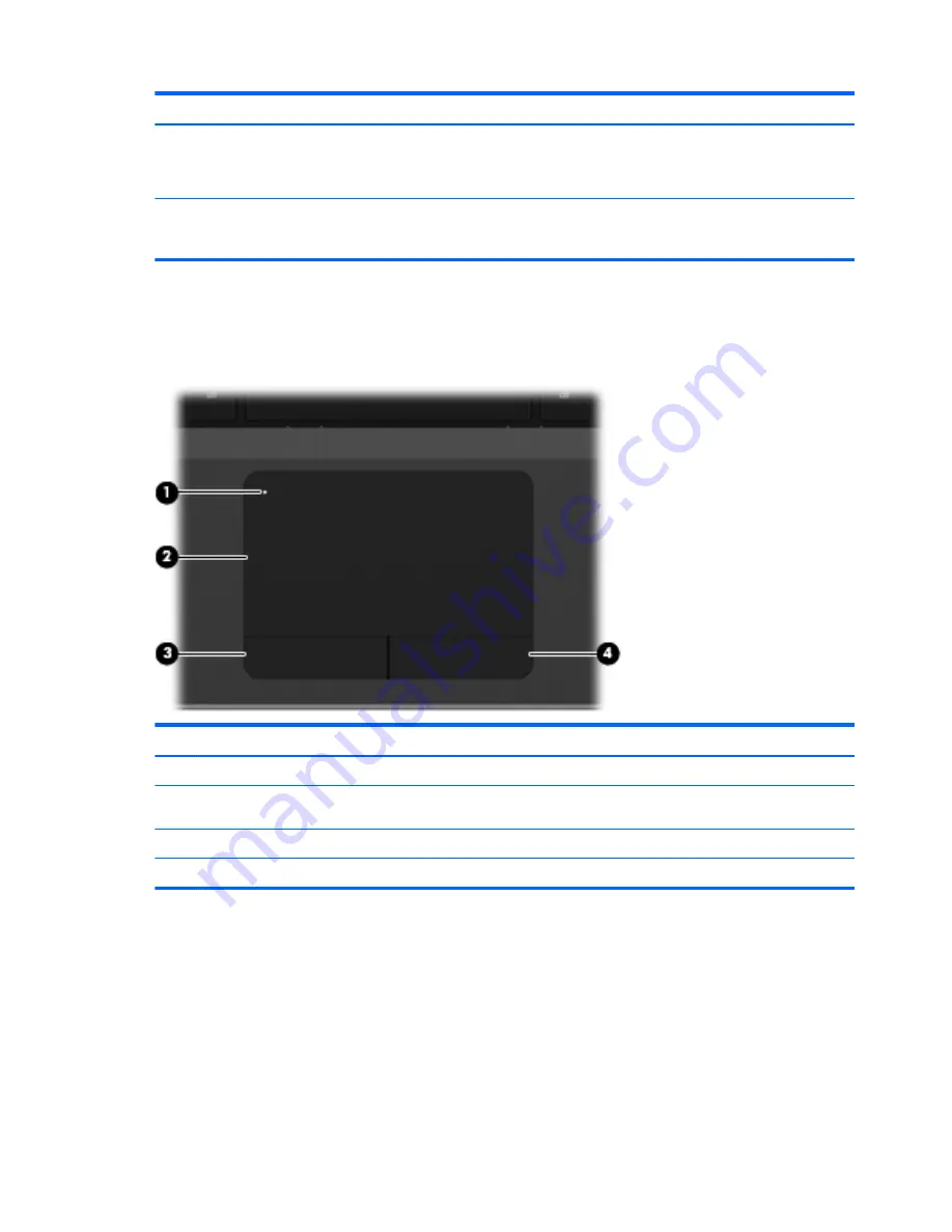
Top

TouchPad

Component

Description

(1)


TouchPad on/off button 

Turns the TouchPad on and off.

(2)


TouchPad

Moves the pointer and selects or activates items on the
screen.

(3)


Left TouchPad button

Functions like the left button on an external mouse.

(4)


Right TouchPad button

Functions like the right button on an external mouse.

8

Chapter 2   External component identification

Summary of Contents for ProBook 4535s

Page 1: ...HP ProBook 4535s Notebook PC Maintenance and Service Guide ...

Page 2: ...n in the United States and or other countries SD Logo is a trademark of its proprietor The information contained herein is subject to change without notice The only warranties for HP products and services are set forth in the express warranty statements accompanying such products and services Nothing herein should be construed as constituting an additional warranty HP shall not be liable for techn...

Page 3: ...llow another hard surface such as an adjoining optional printer or a soft surface such as pillows or rugs or clothing to block airflow Also do not allow the AC adapter to contact the skin or a soft surface such as pillows or rugs or clothing during operation The computer and the AC adapter comply with the user accessible surface temperature limits defined by the International Standard for Safety o...

Page 4: ...iv Safety warning notice ...

Page 5: ... Bottom 17 3 Illustrated parts catalog 18 Service tag 18 Computer major components 19 Display components 25 Plastics Kit 26 Cable Kit 27 Mass storage devices 27 Miscellaneous parts 28 Sequential part number listing 29 4 Removal and replacement procedures 35 Preliminary replacement requirements 35 Tools required 35 Service considerations 35 Plastic parts 35 Cables and connectors 36 Drive handling 3...

Page 6: ...Top cover 59 Card reader board 64 Speaker assembly 65 Quick Launch board 67 Power button board 68 Modem module 70 Lid switch 72 USB board 73 RJ 11 jack cable 75 System board 76 RTC battery 79 Fan 81 Heat sink 83 Processor 85 Power cable 87 Display assembly 89 5 Computer Setup BIOS and System Diagnostics 98 Using Computer Setup 98 Starting Computer Setup 98 Navigating and selecting in Computer Setu...

Page 7: ... and recovery 110 Windows 7 110 Backing up your information 110 Performing a system recovery 111 Using the Windows recovery tools 112 Using f11 recovery tools 112 Using a Windows 7 operating system DVD purchased separately 113 Windows Vista 114 Backing up your information 114 Performing a recovery 115 Using the Windows recovery tools 115 Using f11 recovery tools 116 Using a Windows Vista operating...

Page 8: ...viii ...

Page 9: ... Base 1 MB L2 cache dual core 45W Graphics HD 6480G AMD A4 3300M 2 50 GHz Max 1 9 GHz Base 2 MB L2 cache dual core 45W Graphics HD 6480G AMD E2 3000M 2 40 GHz Max 1 8 GHz Base 1 MB L2 cache dual core 35W Graphics HD 6380G Fusion Controller Hub Chipset AMD A70M FCH Graphics AMD UMA Processor specific see Processors AMD Discrete Graphics A6 3400M Graphic branding HD 6540G2 A4 3300M Graphic branding ...

Page 10: ...e upgradeable memory module slots supporting up to 8 GB of RAM Supports dual channel memory PC3 10600 1333 MHz DDR3 Supports the following configurations 8192 4096 2 4096 2048 2 4096 4096 1 3072 2048 1024 2048 2048 1 2048 1024 2 1024 1024 1 Hard drives Supports 7 mm 9 5 mm 12 7 mm 2 5 in SATA hard drives with HP 3D DriveGuard Customer accessible Supports the following drives 750 GB 7200 rpm 750 GB...

Page 11: ... Modem option Ethernet Realtek RTL8151EH CG 10 100 1000 S3 S4 S5 wake on LAN AC mode only Ethernet cable not included Wireless Integrated WLAN options by way of wireless module Two WLAN antennas built into display assembly Supports no WLAN option Supports the following WLAN formats Ralink 802 11 b g n 1 1 Realtek 802 11 b g n 1 1 Atheros 802 11 b g n BT Combo Ralink 802 11 a b g n BT Combo Realtek...

Page 12: ... Dsub 15 pin supporting 1600 1200 external resolution at 75 GHz hot plug unplug with auto detect HDMI Multi pin AC port Keyboard pointing devices Full sized keyboard with numeric keypad Touchpad includes supports 2 way scroll with legend taps enabled by default 2 finger scrolling and zoom enabled by default Power requirements Smart AC adapter with localized cable plug support 3 wire plug with grou...

Page 13: ...10 Starter Windows 7 Professional 64 with Microsoft Office 2010 Personal Windows 7 Professional 64 with Microsoft Office 2010 Home Business Windows 7 Professional 64 with Microsoft Office 2010 Professional Windows 7 Home Premium 32 with Microsoft Office 2010 Starter EDGI Windows 7 Home Premium 32 with Microsoft Office 2010 Starter Windows 7 Home Premium 32 with Microsoft Office 2010 Personal Windo...

Page 14: ...e Premium 32 Windows 7 Starter DRDVD Windows 7 Windows Vista through Service only Web only support Windows XP Professional Windows Vista Home Basic 32 Certified Microsoft WHQL Serviceability End user replaceable parts AC adapter Battery system Hard drive Memory module Optical drive WLAN module WWAN module SIM Keyboard 6 Chapter 1 Product description ...

Page 15: ...play switch is not visible from the outside of the computer 3 WWAN antennas 2 select models only Send and receive wireless signals to communicate with wireless wide area networks WWAN 4 WLAN antennas 2 Send and receive wireless signals to communicate with wireless local area networks WLAN 5 Internal microphone s 1 or 2 depending on model Record sound 6 Webcam light select models only On The webcam...

Page 16: ...wireless regulatory notices refer to the section of the Regulatory Safety and Environmental Notices that applies to your country or region These notices are located in Help and Support Top TouchPad Component Description 1 TouchPad on off button Turns the TouchPad on and off 2 TouchPad Moves the pointer and selects or activates items on the screen 3 Left TouchPad button Functions like the left butt...

Page 17: ...on Blinking The computer is in the Sleep state Off The computer is off or in Hibernation 4 QuickWeb light Blinking QuickWeb is on Off QuickWeb is off NOTE For more information refer to the HP QuickWeb software Help 5 Wireless light White An integrated wireless device such as a wireless local area network WLAN device and or a Bluetooth device is on Amber All wireless devices are off Top 9 ...

Page 18: ...uter is in Hibernation press the button briefly to exit Hibernation If the computer has stopped responding and Windows shutdown procedures are ineffective press and hold the power button for at least 5 seconds to turn off the computer To learn more about your power settings Windows 7 Select Start Control Panel System and Security Power Options Windows Vista Select Start Control Panel System and Ma...

Page 19: ... QuickWeb press the button to open the default Web browser NOTE For more information refer to the HP QuickWeb software Help If your computer does not have HP QuickWeb software the button does not perform any action or function 3 Wireless button Turns the wireless feature on or off but does not establish a wireless connection 4 Fingerprint reader select models only Allows a fingerprint logon to Win...

Page 20: ...that is active when the computer is turned off is reinstated when the computer is turned back on 4 fn key Executes frequently used system functions when pressed in combination with a function key the num lk key or the esc key 5 Windows logo key Displays the Windows Start menu 6 Embedded numeric keypad select models only When the keypad is turned on it can be used like an external numeric keypad Ea...

Page 21: ... numeric keypad NOTE The keypad function that is active when the computer is turned off remains on when the computer is turned back on 4 Integrated numeric keypad select models only When the num lk has been enabled it can be used like an external numeric keypad 5 fn key Executes frequently used system functions when pressed in combination with a function key or the esc key 6 Windows logo key Displ...

Page 22: ...D Card Secure Digital SD Card Micro 3 Audio out headphone jack Connects optional powered speakers headphones earbuds a headset or television audio WARNING To reduce the risk of personal injury adjust the volume before putting on headphones earbuds or a headset For additional safety information refer to the Regulatory Safety and Environmental Notices NOTE When a device is connected to the jack the ...

Page 23: ...el When the battery reaches a critical battery level the battery light begins blinking rapidly Off The battery is fully charged 3 Power connector Connects an AC adapter 4 Vent Enables airflow to cool internal components NOTE The computer fan starts up automatically to cool internal components and prevent overheating It is normal for the internal fan to cycle on and off during routine operation 5 E...

Page 24: ... Description 1 USB 2 0 ports 2 Connect optional USB devices 2 RJ 11 modem jack select models only Connects a modem cable 3 Optical drive select models only Reads and writes select models only to an optical disc 4 Optical drive light Lights when the optical drive is active 5 Optical drive eject button Releases the optical drive disc tray 16 Chapter 2 External component identification ...

Page 25: ...nt overheating It is normal for the internal fan to cycle on and off during routine operation 5 Hard drive bay and wireless and memory module compartments Holds the hard drive and also contains the wireless LAN module slot and the memory module slot CAUTION To prevent an unresponsive system replace the wireless module only with a wireless module authorized for use in the computer by the government...

Page 26: ...omputer Serial number s n 2 This is an alphanumeric identifier that is unique to each product Part number Product number p n 3 This number provides specific information about the product s hardware components The part number helps a service technician to determine what components and parts are needed Warranty period 4 This number describes the duration in years of the warranty period for the compu...

Page 27: ...Computer major components Computer major components 19 ...

Page 28: ...ton board 646294 001 6 Quick Launch board 646296 001 7 Modem module NOTE The modem module spare part kit does not include a modem module cable The modem module cable is included in the Cable Kit spare part number 646303 001 See Cable Kit on page 27 for more Cable Kit spare part number information 628824 001 8 Lid switch board 646289 001 9 Speaker assembly includes housing 646298 001 10 System boar...

Page 29: ...m Guatemala Guinea Guinea Bissa Guyana Haiti Honduras Hong Kong Hungary Iceland India Indonesia Ireland Israel Italy Ivory Coast Jamaica Japan Jordan Kazakhstan Kenya Kiribati Kuwait Kyrgyzstan Laos Latvia Lebanon Lesotho Liberia Liechtenstein Lithuania Luxembourg Macedonia Madagascar Malawi Malaysia Maldives Mali Malta Marshall Islands Martinique Mauritania Mauritius Mexico Micronesia Monaco Mong...

Page 30: ...nited States the US Virgin Islands Uzbekistan Vanuatu Venezuela Vietnam Yemen Zaire Zambia and Zimbabwe 602993 001 Ralink 5390GN 802 11b g n 1x1 WiFi Adapter for use in Afghanistan Albania Algeria Andorra Angola Antigua and Barbuda Argentina Armenia Aruba Australia Austria Azerbaijan Bahamas Bahrain Baltics Bangladesh Barbados Belarus Belgium Belize Benin Bermuda Bhutan Bolivia Bosnia and Herzegov...

Page 31: ...re Zambia and Zimbabwe 630813 001 Realtek 8188GN 802 11b g n 1x1 WiFi Adapter for use in Afghanistan Albania Algeria Andorra Angola Antigua and Barbuda Argentina Armenia Aruba Australia Austria Azerbaijan Bahamas Bahrain Baltics Bangladesh Barbados Belarus Belgium Belize Benin Bermuda Bhutan Bolivia Bosnia and Herzegovina Botswana Brazil the British Virgin Islands Brunei Bulgaria Burkina Faso Buru...

Page 32: ...00 GB 7200 rpm 634925 001 500 GB 5400 rpm 634638 001 320 GB 5400 rpm 2 5 in 622643 001 320 GB 5400 rpm 7 mm 645193 001 320 GB 7200 rpm 2 5 in 641672 001 320 GB 7200 rpm 7 mm 634862 001 250 GB 7200 rpm 2 5 in 635225 001 250 GB 7200 rpm 7 mm 634861 001 250 GB 5400 rpm 2 5 in 622641 001 250 GB 5400 rpm 7 mm 645191 001 22 Optical drive includes bracket bezel and screws Blu ray BD R RE DVD RW SuperMult...

Page 33: ...rt number 1 Display bezel For use with models with a webcam 646266 001 For use with models without a webcam 646265 001 2 Display hinge covers 646281 001 3 Webcam module 642795 001 Microphone module not illustrated 642797 001 Display components 25 ...

Page 34: ...splay Cable Kit For use in models without a webcam 605766 001 For use in models with a webcam 646273 001 8 WLAN antennas 646276 001 9 WWAN antennas 646278 001 10 Display enclosure 646269 001 Plastics Kit Item Description Spare part number Plastics Kit 646309 001 1 RJ 11 holder 2 Secure Digital card protective insert 3 ExpressCard slot protective insert 4 Optical drive protective insert 26 Chapter ...

Page 35: ...D R RW DL Drive 647952 001 DVD RW and CD RW SuperMulti DL Combo Drive 647950 001 DVD ROM Drive 647949 001 Hard drives 750 GB 7200 rpm 633252 001 750 GB 5400 rpm 634250 001 640 GB 5400 rpm 603785 001 500 GB 7200 rpm 634925 001 500 GB 5400 rpm 634638 001 320 GB 5400 rpm 2 5 in 622643 001 320 GB 5400 rpm 7 mm 645193 001 320 GB 7200 rpm 2 5 in 641672 001 320 GB 7200 rpm 7 mm 634862 001 250 GB 7200 rpm...

Page 36: ... Middle East and Africa 490371 021 For use in Israel 490371 BB1 For use in Italy 490371 061 For use in South Africa 490371 AR1 For use in Switzerland 490371 111 For use in the United Kingdom 490371 031 For use in the United States 490371 001 Rubber Kit includes SIM bumper and feet 646307 001 Screw Kit 646305 001 HP keyed cable lock 626729 001 Mouse optical 2 button 390632 001 HP optical travel mou...

Page 37: ...mark Djibouti Dominica the Dominican Republic East Timor Ecuador Egypt El Salvador Equitorial Guinea Eritrea Estonia Ethiopia Fiji Finland France French Guiana Gabon Gambia Georgia Germany Ghana Gibraltar Greece Grenada Guadeloupe Guam Guatemala Guinea Guinea Bissa Guyana Haiti Honduras Hong Kong Hungary Iceland India Indonesia Ireland Israel Italy Ivory Coast Jamaica Japan Jordan Kazakhstan Kenya...

Page 38: ...illes the Netherlands New Zealand Nicaragua Niger Nigeria Norway Oman Pakistan Palau Panama Papua New Guinea Paraguay Puerto Rico Peru Philippines Poland Portugal Qatar Republic of Moldova Romania Russia Rwanda Samoa San Marino Sao Tome and Principe Saudi Arabia Senegal Serbia and Montenegro Seychelles Sierra Leone Singapore Slovakia Slovenia Solomon Islands Somalia South Africa South Korea Spain ...

Page 39: ...e in Afghanistan Albania Algeria Andorra Angola Antigua and Barbuda Argentina Armenia Aruba Australia Austria Azerbaijan Bahamas Bahrain Baltics Bangladesh Barbados Belarus Belgium Belize Benin Bermuda Bhutan Bolivia Bosnia and Herzegovina Botswana Brazil the British Virgin Islands Brunei Bulgaria Burkina Faso Burundi Cambodia Cameroon Canada Cape Verde the Cayman Islands Central African Republic ...

Page 40: ...co Mongolia Montenegro Morocco Mozambique Namibia Nauru Nepal the Nether Antilles the Netherlands New Zealand Nicaragua Niger Nigeria Norway Oman Pakistan Palau Panama Papua New Guinea Paraguay Puerto Rico Peru Philippines Poland Portugal Qatar Republic of Moldova Romania Russia Rwanda Samoa San Marino Sao Tome and Principe Saudi Arabia Senegal Serbia and Montenegro Seychelles Sierra Leone Singapo...

Page 41: ...Portugal 646300 141 Keyboard for use in Turkey 646300 161 Keyboard for use in Latin America 646300 171 Keyboard for use in Saudi Arabia 646300 211 Keyboard for use Hungary 646300 251 Keyboard for use in Russia 646300 261 Keyboard for use in Bulgaria 646300 A41 Keyboard for use in Belgium 646300 A81 Keyboard for use in the Czech Republic 646300 B31 Keyboard for use in the Netherlands and Europe 646...

Page 42: ...odels with 512 MB of discrete memory 654308 001 System board for use in models with UMA graphics without WWAN 654309 001 System board for use in models with UMA graphics with WWAN 654310 001 Heat sink for use in computers with discrete graphics 654311 001 Heat sink for use in computers with UMA graphics 654313 001 39 6 cm 15 6 inch display assembly HD anti glare with webcam 654315 001 39 6 cm 15 6...

Page 43: ... some of the considerations that you must keep in mind during disassembly and assembly procedures NOTE As you remove each subassembly from the computer place the subassembly and all accompanying screws away from the work area to prevent damage Plastic parts CAUTION Using excessive force during disassembly and reassembly can damage plastic parts Use care when handling the plastic parts Apply pressu...

Page 44: ...erting a hard drive shut down the computer If you are unsure whether the computer is off or in Hibernation turn the computer on and then shut it down through the operating system Before handling a drive be sure that you are discharged of static electricity While handling a drive avoid touching the connector Before removing a diskette drive or optical drive be sure that a diskette or disc is not in...

Page 45: ...ons Keep components in their electrostatic safe containers until you are ready to install them Use nonmagnetic tools Before touching an electronic component discharge static electricity by using the guidelines described in this section Avoid touching pins leads and circuitry Handle electronic components as little as possible If you remove a component place it in an electrostatic safe container The...

Page 46: ...nd that proper materials are selected to avoid static charging When grounding is not possible use an ionizer to dissipate electric charges Workstation guidelines Follow these grounding workstation guidelines Cover the workstation with approved static shielding material Use a wrist strap connected to a properly grounded work surface and use properly grounded tools and equipment Use conductive field...

Page 47: ...e between the operator and ground To be effective the conductive strips must be worn in contact with the skin The following grounding equipment is recommended to prevent electrostatic damage Antistatic tape Antistatic smocks aprons and sleeve protectors Conductive bins and other assembly or soldering aids Nonconductive foam Conductive tabletop workstations with ground cords of one megohm resistanc...

Page 48: ...e computer serial number and model description provided on the service tag Product name 1 This is the product name affixed to the front of the computer Serial number s n 2 This is an alphanumeric identifier that is unique to each product Part number Product number p n 3 This number provides specific information about the product s hardware components The part number helps a service technician to d...

Page 49: ... the operating system 2 Disconnect all external devices connected to the computer 3 Disconnect the power from the computer by first unplugging the power cord from the AC outlet and then unplugging the AC adapter from the computer Remove the battery 1 Position the computer upside down on a flat surface with the battery bay toward you 2 Slide the battery release latches 1 to release the battery 3 Pi...

Page 50: ...e computer on and then shut it down through the operating system 2 Disconnect all external devices connected to the computer 3 Disconnect the power from the computer by first unplugging the power cord from the AC outlet and then unplugging the AC adapter from the computer 4 Remove the battery see Battery on page 41 Remove the SIM 1 Position the computer upside down with the battery bay toward you ...

Page 51: ... the computer by first unplugging the power cord from the AC outlet and then unplugging the AC adapter from the computer 4 Remove the battery see Battery on page 41 Remove the bottom door 1 Position the computer upside down on a flat surface with the battery bay toward you 2 Remove the locking screw if installed 1 and slide the bottom door release latches 2 to release the door 3 Slide the door tow...

Page 52: ...hrough the operating system 2 Disconnect all external devices connected to the computer 3 Disconnect the power from the computer by first unplugging the power cord from the AC outlet and then unplugging the AC adapter from the computer 4 Remove the battery see Battery on page 41 5 Remove the bottom door see Bottom door on page 43 Remove the optical drive 1 Position the computer upside down with th...

Page 53: ...he optical drive with the rear toward you 6 Remove the two Phillips PM2 0 3 0 screws 1 that secure the optical drive bracket to the optical drive 7 Remove the optical drive bracket 2 Reverse this procedure to install an optical drive Component replacement procedures 45 ...

Page 54: ...rews 647944 001 Before disassembling the computer follow these steps 1 Shut down the computer If you are unsure whether the computer is off or in Hibernation turn the computer on and then shut it down through the operating system 2 Disconnect all external devices connected to the computer 3 Disconnect the power from the computer by first unplugging the power cord from the AC outlet and then unplug...

Page 55: ...r cover down onto the bracket and then lift to open the Mylar cover 2 6 Remove the two Phillips PM3 0 3 0 hard drive bracket screws 3 from each side of the hard drive 4 total screws 7 Rotate the hard drive upward and remove it from the bracket 4 Reverse this procedure to reassemble and install the hard drive Component replacement procedures 47 ...

Page 56: ...6 Under Step 2 Select a Download click the BIOS link 7 Click the link for the most recent BIOS 8 Click the Download button and then follow the on screen instructions Before removing the memory module follow these steps 1 Shut down the computer If you are unsure whether the computer is off or in Hibernation turn the computer on and then shut it down through the operating system 2 Disconnect all ext...

Page 57: ...rtion into the memory module slot NOTE The computer uses two memory sockets The top socket houses the expansion memory module and is shown in the following image The bottom socket houses the primary memory module The removal procedure is the same for both memory sockets Reverse this procedure to install a memory module Component replacement procedures 49 ...

Page 58: ...omputer by first unplugging the power cord from the AC outlet and then unplugging the AC adapter from the computer 4 Remove the battery see Battery on page 41 5 Remove the SIM see SIM on page 42 6 Remove the bottom door see Bottom door on page 43 Remove the WWAN module 1 Position the computer upside down with the battery bay toward you 2 Disconnect the WWAN antenna cables 1 from the terminals on t...

Page 59: ...event incorrect insertion Figure 4 1 Removing the WWAN module NOTE If the WWAN antennas are not connected to the terminals on the WWAN module the protective sleeves must be installed on the antenna connectors as shown in the following illustration Reverse this procedure to install the WWAN module Component replacement procedures 51 ...

Page 60: ...e the United Arab Emirates the United Kingdom Uruguay the United States the US Virgin Islands Uzbekistan Vanuatu Venezuela Vietnam Yemen Zaire Zambia and Zimbabwe 593127 001 Realtek 8188BC8 802 11a b g n 2x2 WiFi and Bluetooth 3 0 HS Combo Adapter for use in Afghanistan Albania Algeria Andorra Angola Antigua and Barbuda Argentina Armenia Aruba Australia Austria Azerbaijan Bahamas Bahrain Baltics B...

Page 61: ...apan Jordan Kazakhstan Kenya Kiribati Kuwait Kyrgyzstan Laos Latvia Lebanon Lesotho Liberia Liechtenstein Lithuania Luxembourg Macedonia Madagascar Malawi Malaysia Maldives Mali Malta Marshall Islands Martinique Mauritania Mauritius Mexico Micronesia Monaco Mongolia Montenegro Morocco Mozambique Namibia Nauru Nepal the Nether Antilles the Netherlands New Zealand Nicaragua Niger Nigeria Norway Oman...

Page 62: ... WiFi Adapter for use in Afghanistan Albania Algeria Andorra Angola Antigua and Barbuda Argentina Armenia Aruba Australia Austria Azerbaijan Bahamas Bahrain Baltics Bangladesh Barbados Belarus Belgium Belize Benin Bermuda Bhutan Bolivia Bosnia and Herzegovina Botswana Brazil the British Virgin Islands Brunei Bulgaria Burkina Faso Burundi Cambodia Cameroon Canada Cape Verde the Cayman Islands Centr...

Page 63: ...nna cables 1 from the terminals on the WLAN module NOTE The WLAN antenna cable labeled 1 connects to the WLAN module Main terminal labeled 1 The WLAN antenna cable labeled 2 connects to the WLAN module Aux terminal labeled 2 If the computer is equipped with an 802 11a b g n WLAN module the yellow WLAN antenna cable connects to the middle terminal on the WLAN module 3 Remove the two Phillips PM2 0 ...

Page 64: ...otch 4 to prevent incorrect insertion NOTE If the WLAN antennas are not connected to the terminals on the WLAN module the protective sleeves must be installed on the antenna connectors as shown in the following illustration Reverse this procedure to install the WLAN module 56 Chapter 4 Removal and replacement procedures ...

Page 65: ...all external devices connected to the computer 3 Disconnect the power from the computer by first unplugging the power cord from the AC outlet and then unplugging the AC adapter from the computer 4 Remove the battery see Battery on page 41 5 Remove the bottom door see Bottom door on page 43 Remove the keyboard 1 Position the computer upside down with the front toward you 2 Remove the two Phillips P...

Page 66: ... with the front toward you 6 Open the computer as far as possible 7 Lift and rotate the keyboard 1 until it rests on the palm rest 2 NOTE Some units have double sided tape securing the keyboard to the top cover 8 Lift the keyboard connector latch 1 9 Disconnect the keyboard cable from the system board 2 58 Chapter 4 Removal and replacement procedures ...

Page 67: ...se steps 1 Shut down the computer If you are unsure whether the computer is off or in Hibernation turn the computer on and then shut it down through the operating system 2 Disconnect all external devices connected to the computer 3 Disconnect the power from the computer by first unplugging the power cord from the AC outlet and then unplugging the AC adapter from the computer 4 Remove the battery s...

Page 68: ... computer 1 4 rubber screw covers 2 10 Torx T8M2 5 6 0 screws 3 Remove the following screws that secure the top cover to the computer 1 3 Phillips PM2 0 4 0 screws from the optical drive bay 2 3 Phillips PM2 5 2 5 broadhead screws from the battery bay 4 Turn the computer upright and open it as far as possible 60 Chapter 4 Removal and replacement procedures ...

Page 69: ...he connector latch 1 and disconnect the function board cable 2 Disconnect the speaker cable 3 Lift the connector latch 4 and disconnect the power button board cable 5 Lift the connector latch 6 and disconnect the fingerprint reader board cable 7 7 Position the computer on its side with the display open Component replacement procedures 61 ...

Page 70: ...rd you 10 To remove the top cover pull up on the top of the top cover 1 pull upward on the left 2 and right sides 3 and then lift the bottom of the top cover 4 to remove it enough to access the card reader cable underneath 11 Lift the front of the top cover slightly to gain access to the cable and connector underneath 62 Chapter 4 Removal and replacement procedures ...

Page 71: ...12 Lift the connector latch 1 disconnect the card reader cable 2 and then lift the top cover from the computer 3 Reverse this procedure to install the top cover Component replacement procedures 63 ...

Page 72: ...n unplugging the AC adapter from the computer 4 Remove the battery see Battery on page 41 5 Remove the following components a Bottom door see Bottom door on page 43 b Optical drive see Optical drive on page 44 c Keyboard see Keyboard on page 57 d Top cover see Top cover on page 59 Remove the card reader 1 Position the top cover upside down with the front toward you 2 Remove the tape that secures t...

Page 73: ... turn the computer on and then shut it down through the operating system 2 Disconnect all external devices connected to the computer 3 Disconnect the power from the computer by first unplugging the power cord from the AC outlet and then unplugging the AC adapter from the computer 4 Remove the battery see Battery on page 41 5 Remove the following components a Bottom door see Bottom door on page 43 ...

Page 74: ... Remove the power button board cable from atop the left speaker 2 4 Remove the four Phillips PM2 0 4 0 screws 3 that secure the speakers to the computer 5 Lift the speaker from the top cover 4 while removing the cable from its routing path in the top cover 5 Reverse this procedure to install the speaker assembly 66 Chapter 4 Removal and replacement procedures ...

Page 75: ...from the AC outlet and then unplugging the AC adapter from the computer 4 Remove the battery see Battery on page 41 5 Remove the following components a Bottom door see Bottom door on page 43 b Optical drive see Optical drive on page 44 c Keyboard see Keyboard on page 57 d Top cover see Top cover on page 59 e Speakers see Speaker assembly on page 65 Remove the Quick Launch board 1 Position the top ...

Page 76: ... in Hibernation turn the computer on and then shut it down through the operating system 2 Disconnect all external devices connected to the computer 3 Disconnect the power from the computer by first unplugging the power cord from the AC outlet and then unplugging the AC adapter from the computer 4 Remove the battery see Battery on page 41 5 Remove the following components a Bottom door see Bottom d...

Page 77: ... the front toward you 2 Remove the two Phillips PM2 0 4 0 screws 1 that secure the board to the top cover 3 Lift the board up at an angle 2 and then remove it from the top cover 3 Reverse this procedure to install the power button board Component replacement procedures 69 ...

Page 78: ...xternal devices connected to the computer 3 Disconnect the power from the computer by first unplugging the power cord from the AC outlet and then unplugging the AC adapter from the computer 4 Remove the battery see Battery on page 41 5 Remove the following components a Bottom door see Bottom door on page 43 b Optical drive see Optical drive on page 44 c Keyboard see Keyboard on page 57 d Top cover...

Page 79: ...4 Disconnect the modem module cable 3 from the modem module Reverse this procedure to install the modem module Component replacement procedures 71 ...

Page 80: ...power cord from the AC outlet and then unplugging the AC adapter from the computer 4 Remove the battery see Battery on page 41 5 Remove the following components a Bottom door see Bottom door on page 43 b Optical drive see Optical drive on page 44 c Keyboard see Keyboard on page 57 d Top cover see Top cover on page 59 Remove the lid switch 1 Position the computer upright with the front toward you 2...

Page 81: ...m the AC outlet and then unplugging the AC adapter from the computer 4 Remove the battery see Battery on page 41 5 Remove the following components a Bottom door see Bottom door on page 43 b Optical drive see Optical drive on page 44 c Keyboard see Keyboard on page 57 d Top cover see Top cover on page 59 Remove the USB board 1 Position the computer upright with the front toward you 2 Lift the syste...

Page 82: ...4 Lift the board and cable straight up out of the computer 4 Reverse this procedure to install the USB board 74 Chapter 4 Removal and replacement procedures ...

Page 83: ...the AC outlet and then unplugging the AC adapter from the computer 4 Remove the battery see Battery on page 41 5 Remove the following components a Bottom door see Bottom door on page 43 b Optical drive see Optical drive on page 44 c Modem module see Modem module on page 70 d Keyboard see Keyboard on page 57 e Top cover see Top cover on page 59 f USB board see USB board on page 73 Remove the RJ 11 ...

Page 84: ... in models with UMA graphics without WWAN 654308 001 Before removing the system board follow these steps 1 Shut down the computer If you are unsure whether the computer is off or in Hibernation turn the computer on and then shut it down through the operating system 2 Disconnect all external devices connected to the computer 3 Disconnect the power from the computer by first unplugging the power cor...

Page 85: ...module see WLAN Bluetooth combo card on page 52 WWAN module see WWAN module on page 50 Modem module see Modem module on page 70 Processor see Processor on page 85 Remove the system board 1 Position the computer upright with the front toward you 2 Disconnect the webcam cable 1 and the display cable 2 from the system board and remove the cables from the routing clip 3 3 Remove the Phillips PM2 5 5 0...

Page 86: ...stem board disconnect the battery connector cable 1 from the system board 7 Disconnect the smaller power cable 2 and the larger power cable 3 from the system board 8 Lift the system board out of the computer 4 Reverse this procedure to install the system board 78 Chapter 4 Removal and replacement procedures ...

Page 87: ...om the computer 4 Remove the battery see Battery on page 41 5 Remove the following components a Bottom door see Bottom door on page 43 b Hard drive see Hard drive on page 46 c Optical drive see Optical drive on page 44 d WLAN module see WLAN Bluetooth combo card on page 52 e WWAN module see WWAN module on page 50 f Fan see Fan on page 81 g Heat sink see Heat sink on page 83 h Keyboard see Keyboard...

Page 88: ...3 Lift the battery from the system board 2 Reverse this procedure to install the RTC battery 80 Chapter 4 Removal and replacement procedures ...

Page 89: ...tery see Battery on page 41 5 Remove the following components a Bottom door see Bottom door on page 43 b Hard drive see Hard drive on page 46 c Optical drive see Optical drive on page 44 d WLAN module see WLAN Bluetooth combo card on page 52 e WWAN module see WWAN module on page 50 f Fan see Fan on page 81 g Heat sink see Heat sink on page 83 h Keyboard see Keyboard on page 57 i Top cover see Top ...

Page 90: ...fan is controlled by a temperature sensor and is designed to turn on automatically when high temperature conditions exist These conditions are affected by high external temperatures system power consumption power management battery conservation configurations battery fast charging and software requirements Exhaust air is displaced through the ventilation grill located on the left side of the compu...

Page 91: ...tlet and then unplugging the AC adapter from the computer 4 Remove the battery see Battery on page 41 5 Remove the following components a Bottom door see Bottom door on page 43 b Hard drive see Hard drive on page 46 c Optical drive see Optical drive on page 44 d WLAN module see WLAN Bluetooth combo card on page 52 e WWAN module see WWAN module on page 50 f Fan see Fan on page 81 g Heat sink see He...

Page 92: ... clean thermal material from the surface of the system board 1 and heat sink 2 each time you remove the heat sink All heat sink and processor spare part kits include thermal material Reverse this procedure to install the heat sink 84 Chapter 4 Removal and replacement procedures ...

Page 93: ...en shut it down through the operating system 2 Disconnect all external devices connected to the computer 3 Disconnect the power from the computer by first unplugging the power cord from the AC outlet and then unplugging the AC adapter from the computer 4 Remove the battery see Battery on page 41 5 Remove the following components a Bottom door see Bottom door on page 43 b Hard drive see Hard drive ...

Page 94: ...screw 1 one half turn counterclockwise until you hear a click 3 Lift the processor 2 straight up and remove it NOTE The gold triangle 3 on the processor must be aligned with the triangle 4 embossed on the processor slot when you install the processor Reverse this procedure to install the processor 86 Chapter 4 Removal and replacement procedures ...

Page 95: ...ng the AC adapter from the computer 4 Remove the battery see Battery on page 41 5 Remove the following components a Bottom door see Bottom door on page 43 b Hard drive see Hard drive on page 46 c Optical drive see Optical drive on page 44 d WLAN module see WLAN Bluetooth combo card on page 52 e WWAN module see WWAN module on page 50 f Fan see Fan on page 81 g Heat sink see Heat sink on page 83 h K...

Page 96: ...3 Lift the power cable assembly from the computer 2 Reverse this procedure to install the power cable 88 Chapter 4 Removal and replacement procedures ...

Page 97: ...mbly follow these steps 1 Shut down the computer If you are unsure whether the computer is off or in Hibernation turn the computer on and then shut it down through the operating system 2 Disconnect all external devices connected to the computer 3 Disconnect the power from the computer by first unplugging the power cord from the AC outlet and then unplugging the AC adapter from the computer 4 Remov...

Page 98: ...lay cable 2 from the system board and then remove the cables from the clip 3 4 Remove the four Phillips PM2 5 7 0 screws 1 from the hinges noting the grounding wire connected to the screw in the left hinge 2 90 Chapter 4 Removal and replacement procedures ...

Page 99: ...erly Failure to properly route the antennas can result in degradation of the computer s WLAN and WWAN performance 6 If you need to remove the hinge covers from the display hinges pull the hinges straight up and off the display to remove them Display hinge covers are available using spare part number 646281 001 Component replacement procedures 91 ...

Page 100: ... the top 3 of the bezel the inside edges of the left and right sides 4 and then the bottom 5 of the bezel until it disengages from the display enclosure The bezel is available using the following spare part numbers 646265 001 models without a webcam 646266 001 models with a webcam 9 Remove the display bezel 92 Chapter 4 Removal and replacement procedures ...

Page 101: ... module is removed using the same procedure and is available using spare part number 642797 001 11 If it is necessary to replace the display panel remove the four Phillips PM2 5 5 0 screws 1 at the bottom and two Phillips PM2 5 5 0 broadhead screws 2 at the top that secure the panel to the display enclosure 12 Rotate the top of the panel upward 3 The display panel is available using the following ...

Page 102: ...le from the panel 2 The display cable is available using spare part number 605766 001 for models without a webcam 646273 001 for models with a webcam 14 If it is necessary to replace the display hinges remove the four Phillips PM2 5 3 0 screws 1 that secure each display hinge to the display panel 94 Chapter 4 Removal and replacement procedures ...

Page 103: ...hs 3 built into the display enclosure The WLAN antennas are available using spare part number 646276 001 and the WWAN antennas are available using spare part number 646278 001 CAUTION When installing the display assembly be sure that the wireless antenna cables are routed and arranged properly Failure to properly route the antennas can result in degradation of the computer s wireless performance C...

Page 104: ...t a webcam 646273 001 for models with a webcam The webcam cable is available using spare part number 646275 001 Reverse this procedure to reassemble and install the display assembly Note the correct cable routing paths for the antenna cables Make sure you properly route all cables when assembling the computer as shown in the following images Cable routing path top Cable routing path bottom 96 Chap...

Page 105: ...Component replacement procedures 97 ...

Page 106: ... Startup Menu message is displayed at the bottom of the screen 2 Press f10 to enter Computer Setup Navigating and selecting in Computer Setup To navigate and select in Computer Setup follow these steps 1 Turn on or restart the computer and then press esc while the Press the ESC key for Startup Menu message is displayed at the bottom of the screen To select a menu or a menu item use the tab key and...

Page 107: ...uter Setup NOTE Restoring defaults will not change the hard drive mode To return all settings in Computer Setup to the values that were set at the factory follow these steps 1 Turn on or restart the computer and then press esc while the Press the ESC key for Startup Menu message is displayed at the bottom of the screen 2 Press f10 to enter Computer Setup 3 Use a pointing device or the arrow keys t...

Page 108: ...llation download and install a BIOS update only when the computer is connected to reliable external power using the AC adapter Do not download or install a BIOS update while the computer is running on battery power docked in an optional docking device or connected to an optional power source During the download and installation follow these instructions Do not disconnect power from the computer by...

Page 109: ...System Diagnostics Start up test This test analyzes the main computer components that are required to start the computer Run in test This test repeats the start up test and checks for intermittent problems that the start up test does not detect Hard disk test This test analyzes the physical condition of the hard drive and then checks all data in every sector of the hard drive If the test detects a...

Page 110: ... Nonoperating 20 C to 60 C 4 F to 140 F Relative humidity noncondensing Operating 10 to 90 Nonoperating 5 to 95 Maximum altitude unpressurized Operating 15 m to 3 048 m 50 ft to 10 000 ft Nonoperating 15 m to 12 192 m 50 ft to 40 000 ft Shock Operating 125 g 2 ms half sine Nonoperating 200 g 2 ms half sine Random vibration Operating 0 75 g zero to peak 10 Hz to 500 Hz 0 25 oct min sweep rate Nonop...

Page 111: ...ightView Contrast ratio 300 1 typical Anti glare 500 1 BrightView Response time 8 ms Brightness 200 nits typical Viewing angle SVA Backlight LED Luminance uniformity 13 points 1 4 typ 1 6 max Lifetime 1 2 luminance 12 000 hours Color coordinate white 0 313 0 329 Color tolerance White 0 02 Color tolerance R G B 0 03 Color gamut 60 typical 39 6 cm 15 6 in HD display specifications 103 ...

Page 112: ...cal read including setting Single track 1 5 ms 2 ms 3 ms 3 ms 3 ms Average 11 ms 12 ms 13 ms 13 ms 13 ms Maximum 14 ms 22 ms 24 ms 24 ms 24 ms Logical blocks 1 465 149 168 1 250 263 728 1 048 576 000 625 141 400 488 397 168 Disc rotational speed 7200 rpm 7200 rpm or 5400 rpm Operating temperature 5 C to 55 C 41 F to 131 F 1 GB 1 billion bytes when referring to hard drive storage capacity Actual ac...

Page 113: ...D R 9 DVD RW DVD RAM BD R BD RE Access time CD DVD BD ROM Random 180 ms 180 ms 230 ms Maximum Media Capacity read 50 GB Maximum Media Capacity write 8 5 GB Data transfer rate 24X CD ROM 3 600 KB sec 8X DVD 10 800 KB sec 2X BD ROM 9 000 KB sec 16X CD R 3 600 KB sec 16X CD RW 2 400 KB sec 8X DVD R 10 800 KB sec 6X DVD RW 8 100 KB sec 8X DVD R 10 800 KB sec 6X DVD RW 8 100 KB sec 4X DVD R Dual Layer ...

Page 114: ...n Disc diameter Standard disc 12 cm 4 72 in Mini disc 8 cm 3 15 in Disc thickness 1 2 mm 0 047 in Track pitch 0 74 µm Access time CD DVD Random 175 ms 230 ms Full stroke 285 ms 335 ms Audio output level Line out 0 7 Vrms Cache buffer 2 MB Data transfer rate 24X CD ROM 3 600 KB sec 8X DVD ROM 10 800 KB sec 24X CD R 3 600 KB sec 16X CD RW 2 400 KB sec 8X DVD R 10 800 KB sec 4X DVD RW 5 400 KB sec 8X...

Page 115: ...ual Layer HD DVD RW CD R and CD RW DVD R DVD R 9 DVD RW DVD R DVD R 9 DVD RW DVD RAM Access time CD DVD HD Random 170 ms 170 ms 230 ms Cache buffer 8 MB Data transfer rate 24X CD ROM 3 600 KB sec 8X DVD 10 800 KB sec 24X CD R 3 600 KB sec 16X CD RW 2 400 KB sec 8X DVD R 10 800 KB sec 4X DVD RW 5 400 KB sec 8X DVD R 10 800 KB sec 4X DVD RW 5 400 KB sec 2 4X DVD R 9 2 700 KB sec 5X DVD RAM 6 750 KB ...

Page 116: ...ni disc 12 cm 4 72 in 8 cm 3 15 in Disc thickness 1 2 mm 0 047 in Track pitch 0 74 µm Access time CD DVD Random 100 ms 125 ms Full stroke 175 ms 225 ms Audio output level Line out 0 7 Vrms Cache buffer 512 KB Data transfer rate CD R 24X 3600 KB s 150 KB s at 1X CD rate CD RW 10X 1500 KB s 150 KB s at 1X CD rate CD ROM 24X 3600 KB s 150 KB s at 1X CD rate DVD 8X 10 800 KB s 1 352 KB s at 1X DVD rat...

Page 117: ...unning utilities or changing Windows settings Refer to Windows Help and Support for more information After you open Device Manager drill down to a device and double click it to access its properties To access Device Manager in Windows 7 1 Select Start Computer System properties 2 In the left pane click Device Manager To access Device Manager in Windows Vista 1 Select Start Computer System properti...

Page 118: ... backups select models only Creating system restore points Recovering individual files Restoring the computer to a previous state Recovering information using recovery tools NOTE For detailed instructions perform a search for these topics in Help and Support In case of system instability HP recommends that you print the recovery procedures and save them for later use NOTE Windows includes the User...

Page 119: ...iscs number each disc before inserting it into the external drive To create a backup using Backup and Restore NOTE Be sure that the computer is connected to AC power before you start the backup process NOTE The backup process may take over an hour depending on file size and the speed of the computer 1 Select Start All Programs Maintenance Backup and Restore 2 Follow the on screen instructions to s...

Page 120: ...For additional information refer to Using a Windows 7 operating system DVD purchased separately on page 113 3 If the Windows partition and the HP Recovery partition are listed restart the computer and then press f8 before the Windows operating system loads 4 Select Startup Repair 5 Follow the on screen instructions NOTE For additional information on recovering information using the Windows tools p...

Page 121: ...drive contents and reformats the hard drive All files you have created and any software installed on the computer are permanently removed When reformatting is complete the recovery process helps you restore the operating system as well as drivers software and utilities To initiate recovery using a Windows 7 operating system DVD NOTE This process takes several minutes 1 If possible back up all pers...

Page 122: ...upport for more information Backing up your information Recovery after a system failure is as complete as your most current backup You should create your initial backup immediately after software setup As you add new software and data files you should continue to back up your system on a regular basis to maintain a reasonably current backup You can back up your information to an optional external ...

Page 123: ... a Windows Vista operating system DVD purchased separately on page 116 Using the Windows recovery tools To recover information you previously backed up 1 Select Start All Programs Maintenance Backup and Restore Center 2 Follow the on screen instructions to recover your entire computer select models only or your files To recover your information using Startup Repair follow these steps CAUTION Using...

Page 124: ...d the partition select Start Computer NOTE If the HP Recovery partition has been deleted you must recover your operating system and programs using the Windows Vista operating system DVD and the Driver Recovery disc both purchased separately For additional information refer to Using a Windows Vista operating system DVD purchased separately on page 116 3 Turn on or restart the computer and then pres...

Page 125: ... operating system loads 3 When prompted press any keyboard key 4 Follow the on screen instructions 5 Click Next 6 Select Repair your computer 7 Follow the on screen instructions After the repair is completed 1 Eject the Windows Vista operating system DVD and then insert the Driver Recovery disc 2 Install the Hardware Enabling Drivers first and then install Recommended Applications Windows Vista 11...

Page 126: ...ents listed below are applicable to all countries and regions The length of the power cord set must be at least 1 5 m 5 0 ft and no more than 2 0 m 6 5 ft All power cord sets must be approved by an acceptable accredited agency responsible for evaluation in the country or region where the power cord set will be used The power cord sets must have a minimum current capacity of 10 amps and a nominal v...

Page 127: ...t be a two pole grounding type with a NEMA 5 15P 15 A 125 V or NEMA 6 15P 15 A 250 V configuration 3 The appliance coupler flexible cord and wall plug must bear a T mark and registration number in accordance with the Japanese Dentori Law The flexible cord must be Type VCT or VCTF 3 conductor 1 00 mm conductor size The wall plug must be a two pole grounding type with a Japanese Industrial Standard ...

Page 128: ...lly NOTE Materials Disposal This HP product contains mercury in the backlight in the display assembly that might require special handling at end of life Disposal of mercury may be regulated because of environmental considerations For disposal or recycling information contact your local authorities or see the Electronic Industries Alliance EIA Web site at http www eiae org This section provides dis...

Page 129: ... covers 1 and screws 2 that secure the display bezel to the display assembly 2 Lift up and out on the left and right inside edges 1 and the top and bottom inside edges 2 of the display bezel until the bezel disengages from the display assembly 3 Remove the display bezel 3 Display 121 ...

Page 130: ...to the display enclosure 6 Remove the display panel assembly 2 from the display enclosure 7 Position the display panel assembly upside down 8 Remove all screws that secure the display panel frame to the display panel 9 Use a sharp edged tool to cut the tape 1 that secures the sides of the display panel to the display panel frame 122 Chapter 9 Recycling ...

Page 131: ...e display panel 11 Remove the screws 1 that secure the backlight cover to the display panel 12 Lift the top edge of the backlight cover 2 and swing it outward 13 Remove the backlight cover 14 Position the display panel right side up Display 123 ...

Page 132: ...ition the display panel upside down WARNING The backlight contains mercury Exercise caution when removing and handling the backlight to avoid damaging this component and causing exposure to the mercury 17 Remove the backlight frame from the display panel 124 Chapter 9 Recycling ...

Page 133: ... the LCD panel 20 Remove the screws 2 that secure the LCD panel to the display rear panel 21 Release the LCD panel 3 from the display rear panel 22 Release the tape 4 that secures the LCD panel to the display rear panel 23 Remove the LCD panel 24 Recycle the LCD panel and backlight Display 125 ...

Page 134: ...n off 8 wireless 11 C Cable Kit contents 27 spare part number 27 33 cables service considerations 36 caps lock light identifying 9 card reader board removal 64 spare part number 20 33 64 chipset product description 1 components bottom 17 display 7 front 14 left side 15 right side 16 top 8 Computer Setup navigating and selecting 98 restoring factory settings 99 computer specifications 102 connector...

Page 135: ...network 15 RJ 11 modem 16 RJ 45 network 15 K keyboard product description 4 removal 57 spare part numbers 20 33 57 keypad embedded numeric 12 keypad integrated numeric 13 keys esc 12 13 fn 12 13 function 12 13 num lk 12 13 Windows Applications 12 13 Windows logo 12 13 L legacy support USB 98 lid switch removal 72 spare part number 20 33 72 lights Battery 15 caps lock 9 hard drive 14 optical drive ...

Page 136: ...5 network jack identifying 15 RTC battery removal 79 spare part number 24 29 79 Rubber Kit spare part number 34 S Screw Kit spare part number 28 34 Secure Digital card insert illustrated 26 security cable slot identifying 15 security product description 4 service considerations 35 service tag 18 40 serviceability product description 6 setup utility navigating and selecting 98 restoring factory set...

Page 137: ...tem DVD 116 wireless antennas disconnecting 50 55 identifying 7 wireless button identifying 11 wireless compartment identifying 17 wireless light 9 wireless product description 3 WLAN antennas spare part number 26 32 WLAN antennas identifying 7 WLAN Bluetooth combo card removal 52 spare part number 21 29 52 workstation guidelines 38 WWAN antennas identifying 7 spare part number 26 32 WWAN module r...

Reviews: