background image

Removing or Installing 
an Add-in Card 

An add-in card is a circuit board, such as a PCI or an 
AGP card, that fits into a PC add-in card slot. Your PC 
contains several add-in card slots that can be used to 
add components to your PC. The PC component 
configurations vary by model. 


WARNING: Do not overload the system 
by installing add-in cards that draw 
excessive current. The system is designed 
to provide 2 amps (average) of +5 V 
power for each board/card in the 
computer. The total +5 V current draw in a 
fully loaded system (one with all add-in 
card slots filled) must not exceed the total 
number of slots multiplied by 2 amps. 


Removing an Add-in Card 

1


Complete the procedures to prepare the PC, and to 
remove the side panel. See “Opening and Closing 
the PC“ on page 1. 

2


Gently lay the PC on its side. 

3


Inside the PC, locate the add-in card slots on the 
motherboard. 

4


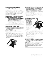
Release the latch that retains the cards by pressing 
the two tabs at the top of the add-in slots inside 
the chassis. Some PCs use a screw instead of the 
retaining latch to secure each add-in card; remove 
the screw. 


5


Holding the card at each end, carefully rock it back 
and forth until the connectors pull free from the 
socket, and then remove the card. Be sure not to 
scrape the card against the other components. 
Store the old card in the anti-static packaging that 
contained your new card. 

6


If you are not replacing the old add-in card with a 
new add-in card, close the open slot by inserting 
the metal slot cover into the opened slot. Replace 
the latch or insert the screw. 


Installing an Add-in Card 

1


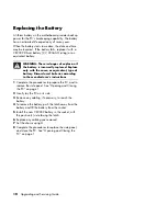
Align the edge of 
the add-in card 
with the slot on the 
chassis and gently 
but firmly press the 
card straight down 
into the add-in 
card slot. The 
whole connector 
should be seated 
properly in the 
card slot. 

2


Replace the latch by pressing in on the square tabs 
on the outside of the chassis. The latch should move 
down so that it locks into position over the cards. If 
it does not latch, check that each card is completely 
seated into its card slot. 

Or 

Insert the retaining screw. 

3


Set the chassis upright. 

4


Complete the procedures to replace the side panel, 
and close the PC. See “Opening and Closing the 
PC“ on page 1. 

NOTE:

 If the new card or device isn’t working, read 

through the card manufacturer’s installation 
instructions, and recheck all connections, including 
those to the card, power supply, keyboard, and 
monitor. 

Upgrading and Servicing Guide    

9


Summary of Contents for Pavilion Ultimate d4900 - Desktop PC

Page 1: ...Upgrading and Servicing Guide ...

Page 2: ...4010 USA Hewlett Packard is a registered trademark of Hewlett Packard Company in the United States of America and other countries regions This product incorporates copyright protection technology that is protected by method claims of certain U S patents and other intellectual property rights owned by Macrovision Corporation and other rights owners Use of this copyright protection technology must b...

Page 3: ...he Front Panel 3 Locating Components Inside the PC 3 Removing and Replacing Drives 3 Removing a Drive 3 Replacing or Adding a Drive 4 Removing a Hard Disk Drive 5 Replacing or Adding a Hard Disk Drive 6 Adding Memory 7 Removing a Memory Module 8 Installing a Memory Module 8 Removing or Installing an Add in Card 9 Removing an Add in Card 9 Installing an Add in Card 9 Replacing the Battery 10 Upgrad...

Page 4: ...iv Upgrading and Servicing Guide ...

Page 5: ...strap and a conductive foam pad when working inside the PC WARNING Always disconnect the modem cord from the telephone system and then disconnect the PC from the power source before removing the front and side panels of the PC Failure to do so before you open the PC or do any procedures can result in personal injury or equipment damage Before Opening the PC 1 Remove any diskette floppy disk memory...

Page 6: ... Side Panel 1 Loosen the two thumbscrews A that secure the panel to the PC chassis 2 Pull back the handle B to free the panel and then lift it off the unit WARNING Beware of sharp edges inside the chassis Replacing the Side Panel 1 Place the side panel on the chassis with the back of the panel extended slightly Ensure the hooks on the top and bottom of the panel fit into the holes in the chassis S...

Page 7: ...disk drive primary with operating system partition K L Additional hard disk drives select models or may be empty Removing and Replacing Drives Your PC has several drives that you can replace or upgrade You can add a drive into an empty drive bay See the preceding topic Locating Components Inside the PC for drive type and location For hard disk drives see Removing a Hard Disk Drive on page 5 Removi...

Page 8: ...e optical drives have two screws on each side the memory card reader and diskette drive have two screws on the left side only You need these screws to install the new drive Replacing or Adding a Drive 1 If necessary remove the existing drive See Removing a Drive on page 3 2 If you are adding a drive to an empty drive bay a Remove the blank plate from the front cover by pushing it forward until it ...

Page 9: ...following illustrations Connecting the optical drive cables NOTE An optical drive may include a sound cable Connect this cable also Connecting the diskette drive cables Connecting the memory card reader drive cables 7 Complete the procedures to replace the front panel replace the side panel and close the PC See Opening and Closing the PC on page 1 Removing a Hard Disk Drive The system hard disk dr...

Page 10: ... disk drive cables Disconnecting the Parallel ATA hard disk drive cables 4 Release the drive from the cage by lifting the tab 1 on the latch for the hard disk drive cage and then sliding 2 the drive out of the cage The latch secures the drive in the cage in the chassis Be careful to touch only the sides of the drive 5 If you are replacing the old drive with a new drive remove the four guide screws...

Page 11: ...Complete the procedures to replace the side panel and close the PC See Opening and Closing the PC on page 1 Adding Memory Your PC comes with random access memory RAM which temporarily stores data and instructions on your PC The PC ships with one or more memory modules but you can replace the existing memory module s with higher capacity ones The motherboard contains sockets for DDR DIMMs double da...

Page 12: ... memory module be careful not to touch any of the contacts Doing so may damage the module 1 Open both latches of the memory module socket If you are replacing a memory module put the new memory module in the same memory slot from which the old memory was removed Or If you are adding a memory module install the new module into the socket nearest the preinstalled module and install additional module...

Page 13: ...d carefully rock it back and forth until the connectors pull free from the socket and then remove the card Be sure not to scrape the card against the other components Store the old card in the anti static packaging that contained your new card 6 If you are not replacing the old add in card with a new add in card close the open slot by inserting the metal slot cover into the opened slot Replace the...

Page 14: ...ype of battery Discard used batteries according to the manufacturer s instructions 1 Complete the procedures to prepare the PC and to remove the side panel See Opening and Closing the PC on page 1 2 Gently lay the PC on its side 3 Remove any cabling if necessary to reach the battery 4 To remove the battery push the latch away from the battery and lift the battery from the socket 5 Install the new ...

Page 15: ......

Page 16: ...Part Number 5991 7205 ...

Reviews: