384
[SwitchA-Vlan-interface20] ip address 1.1.3.1 255.255.255.0
2.
Configure Switch B:
# Configure the IP address of VLAN-interface 10.
<SwitchB> system-view
[SwitchB] interface vlan-interface 10
[SwitchB-Vlan-interface10] ip address 1.1.2.2 255.255.255.0
[SwitchB-Vlan-interface10] quit
3.
Configure Switch C:
# Configure the IP address of VLAN-interface 20.
<SwitchC> system-view
[SwitchC] interface vlan-interface 20
[SwitchC-Vlan-interface20] ip address 1.1.3.2 255.255.255.0
[SwitchC-Vlan-interface20] quit
4.
Verify the configuration:
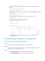
# Telnet to Switch B (1.1.2.2/24) from Switch A. The operation succeeds.
# Telnet to Switch C (1.1.3.2/24) from Switch A. The operation fails.
<SwitchA> telnet 1.1.3.2
Trying 1.1.3.2 ...
Press CTRL+K to abort
Can't connect to the remote host!
# Ping Switch C (1.1.3.2/24) from Switch A. The operation succeeds.
<SwitchA> ping 1.1.3.2
PING 1.1.3.2: 56 data bytes, press CTRL_C to break
Reply from 1.1.3.2: bytes=56 Sequence=1 ttl=255 time=2 ms
Reply from 1.1.3.2: bytes=56 Sequence=2 ttl=255 time=1 ms
Reply from 1.1.3.2: bytes=56 Sequence=3 ttl=255 time=1 ms
Reply from 1.1.3.2: bytes=56 Sequence=4 ttl=255 time=1 ms
Reply from 1.1.3.2: bytes=56 Sequence=5 ttl=255 time=1 ms
--- 1.1.3.2 ping statistics ---
5 packet(s) transmitted
5 packet(s) received
0.00% packet loss
round-trip min/avg/max = 1/1/2 ms
Telnet uses TCP, and ping uses ICMP. The preceding results show that all TCP packets of Switch A
are forwarded to next hop 1.1.2.2, and other packets are forwarded via VLAN-interface 20. The
PBR configuration is effective.
Configuring interface PBR based on packet type
Network requirements
As shown in
, configure PBR on Switch A, so that TCP packets arriving on VLAN-interface 11
are forwarded to next hop 1.1.2.2 and other packets are forwarded according to the routing table.


