background image

HP MSM430, MSM460, MSM466 Dual Radio 802.11n Access Points Quickstart  

3

Installation

Caution:

If the AP will be powered by a user-supplied PoE power injector, 

use only a gigabit-compatible power injector. Although 10/100 PoE-enabled 
switches are compatible, PoE injectors designed for 10/100 networks only are 
not compatible with the AP.

Installation

The AP can be mounted on a wall, a wall-mounted electrical box, or a 
suspended ceiling. The AP Bracket is mounted first and then the AP is attached 
to the bracket. The AP Bracket is two-sided: The AP is installed on the side 
with the UP arrow. The other side with the T-bar clip screw holes faces the wall 
or T-bar.

Mounting directly on a wall

1.

Hold the AP bracket with the UP arrow pointing up against the wall where 
you want to install it. Mark the location of the screw holes (1) [or 5] and 
the cutout area (6).

2.

Drill two holes for the wall anchors, typically 4.7 mm (3/16 inch) in 
diameter.

3.

If necessary, drill a hole for the Ethernet cable in the marked cutout area 
of the AP Bracket. Alternatively, you can feed the Ethernet cable from 
above and through the AP cable channel.

4.

Insert the anchors and tap them flush with the wall surface.

5.

Pull the Ethernet cable through the hole in the wall and the AP Bracket.

6.

Use the mounting screws to attach the AP Bracket to the wall. Proceed to 

Attach the AP 

on page 4.

Mounting on an electrical box

1.

Disconnect power and take any other needed security precautions.

2.

Remove the electrical box cover and any contents. 

3.

Pull the Ethernet cable into the box and through the hole in the AP 
Bracket.

4.

Hold the AP Bracket against the box orienting the UP arrow, and attach 
the AP Bracket to the box using the countersunk screws. Proceed to 

Attach the AP 

on page 4.

Mounting on a suspended ceiling

The AP can be mounted on a suspended ceiling using T-bar clips. Two sets of 
T-bar clips are provided, a 12.5 mm set for recessed tiles and a 4.5 mm set for 
flush-mount tiles. 

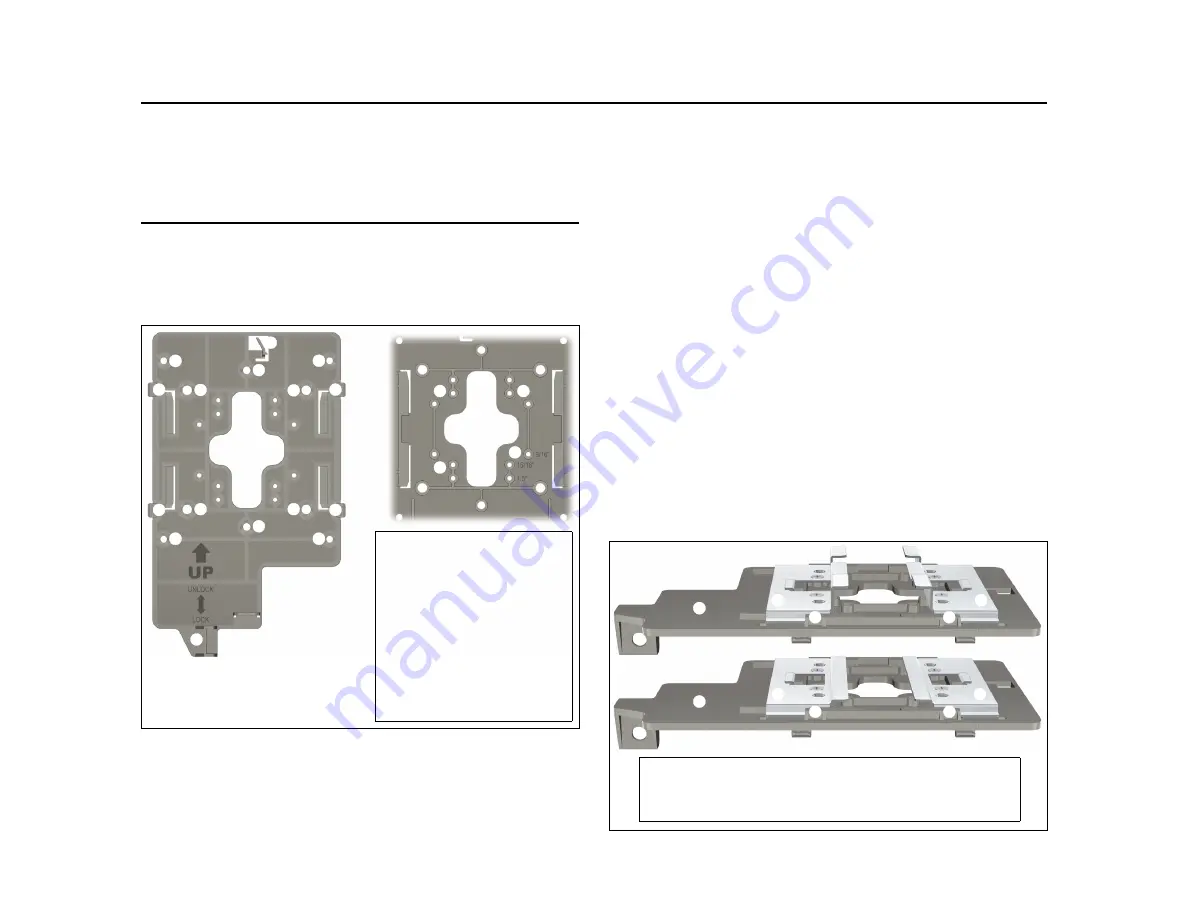
AP Bracket 

(AP side left, wall/

ceiling side right)
1: Adapter Bracket mounting holes
2: AP Bracket latch
3: Electrical box mounting holes 
4: AP retention tabs
5: Drywall mounting holes
6: Cutout area
7: AP Bracket lock tab
8: T-bar clip screw holes

T-bar clips for ceiling mount

1: AP Bracket
2: Recessed tile 12.5 mm T-bar clip

3: Flat tile 4.5 mm T-bar clip
4: AP Bracket T-bar slot

Summary of Contents for MSM430

Page 1: ...ailable at www hp com support manuals Important Operating this AP in controlled mode requires HP MSM7xx software V5 5 2 or later Hardware overview Front view 1 Status LEDs left to right Power Ethernet Radio 1 Radio 2 2 Cable lock hole 3 Retention screw hole Back view 4 Antenna connectors MSM466 only Radio 1 right Radio 2 left 5 Reset button 6 Cable channel 7 AP Bracket tab slot 8 Console port 9 Et...

Page 2: ...he end user is responsible for ensuring that installation and use comply with local safety and radio regulations Surge protection and grounding When connecting antennas installed outdoors to the MSM466 make sure that proper lightning surge protection and grounding precautions are taken according to local electrical code Failure to do so can result in personal injury fire equipment damage or a void...

Page 3: ...thernet cable from above and through the AP cable channel 4 Insert the anchors and tap them flush with the wall surface 5 Pull the Ethernet cable through the hole in the wall and the AP Bracket 6 Use the mounting screws to attach the AP Bracket to the wall Proceed to Attach the AP on page 4 Mounting on an electrical box 1 Disconnect power and take any other needed security precautions 2 Remove the...

Page 4: ...gh which you will pass the Ethernet cable 7 Using the hole in the AP Bracket as a guide drill or cut a hole in the ceiling tile large enough to pass the Ethernet connector through Alternatively you can run a cable outside of the ceiling tile and through the cable channel 8 Slide the ceiling tile to the side Feed the Ethernet cable through the hole in the tile and through the hole in the AP Bracket...

Page 5: ...nel with a controller The controller manages the AP and provides all configuration settings When power is applied the AP establishes a connection to the controller automatically if default settings are used on the AP and the controller and both devices are on the same subnet No further configuration is required After the discovery process is complete and the AP has established a secure management ...

Page 6: ...efault gateway to 192 168 1 1 and DNS server to 192 168 1 1 2 Disable any wireless connection on your computer B Connect the cables and power on the AP 1 Connect the cables If using a PoE switch use Ethernet cables to connect your computer and the AP to an unused factory default PoE switch If using a PoE injector use Ethernet cables to connect your computer to the data in port of the PoE injector ...

Page 7: ...receives a new IP address in place of its default address of 192 168 1 1 upon connecting to the network Use one of the following methods to assign an IP address to the AP Preconfigure the DHCP server to assign a specific IP address to the AP To do this you must specify the AP Ethernet MAC address and a reserved IP address on the DHCP server The AP Ethernet MAC address is printed on the AP label id...

Page 8: ...is set to obtain an IP address automatically 6 By default the AP creates a wireless network named HP in the 5 GHz band for 802 11n and 802 11a users Connect your computer to this wireless network specifying the preshared key you set in step E 2 7 Confirm that you can browse the Internet using the wireless network H Before performing additional configuration Configure your computer LAN port and con...

Reviews: