


Front panel LEDs
63
Enclosure bezel removal
TIP:
(bezel back) on
before removing the bezel from the
enclosure front panel.
You may need to remove the bezel to access front panel components such as disk drive modules and ear kits. Although
disk module LEDs are not visible when the bezel is attached, you can monitor disk behavior from the management
interfaces (see
“Fault isolation methodology” (page 44)
for more information about using LEDs together with event
notification, the CLI, and the SMU for managing the storage system).
While facing the front of the enclosure, grasp the left and right ear covers, such that your fingers cup the bottom of each
ear cover, with thumb at the top of each cover. Gently pull the top of the bezel while applying slight inward pressure
below, to release the bezel from the ball studs.
NOTE:
The bezel should be attached to the enclosure during operation to protect ear circuitry. To reattach the bezel to
the enclosure front panel, follow the instructions provided in
“Enclosure bezel attachment” (page 62)
.
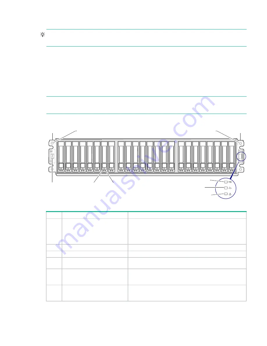
MSA 2050 Array SFF or supported 24-drive expansion enclosure
Figure 27 LEDs: MSA 2050 Array SFF or supported 24-drive expansion enclosure: front panel
1
2
3
Left ear
Right ear
4
5
6
1
2
3
4
5
6
7
8
9 10 11 12 13 14 15 16
17 18 19 20 21 22 23 24
Notes
:
Integers on disks indicate drive slot numbering sequence.
The enlarged detail view at right shows LED icons from the bezel that correspond to chassis LEDs.
Bezel icons for LEDs
Ball stud (two per ear flange)
Ball stud (two per ear flange)
The detail view locator circle (above right) identifies the ear kit that connects to LED light pipes in the bezel (or ear cover).
LED
Description
Definition
1
Enclosure ID
Green — On
Enables you to correlate the enclosure with logical views presented by
management software. Sequential enclosure ID numbering of controller
enclosures begins with the integer 1. The enclosure ID for an attached drive
enclosure is nonzero.
2
Disk drive Online/Activity
.
3
Disk drive Fault/UID
.
4
Unit Identification (UID)
Blue — Identified.
Off — Identity LED off.
5
Heartbeat
Green — The enclosure is powered on with at least one power supply
operating normally.
Off — Both power supplies are off; the system is powered off.
6
Fault ID
Amber — Fault condition exists. The event has been identified, but the
problem needs attention.
Off — No fault condition exists.