background image

2-10

Installing the Switch 2124

Installation Procedures

In

sta

llin

g

 th

e

 Switc

h

 2124

4.

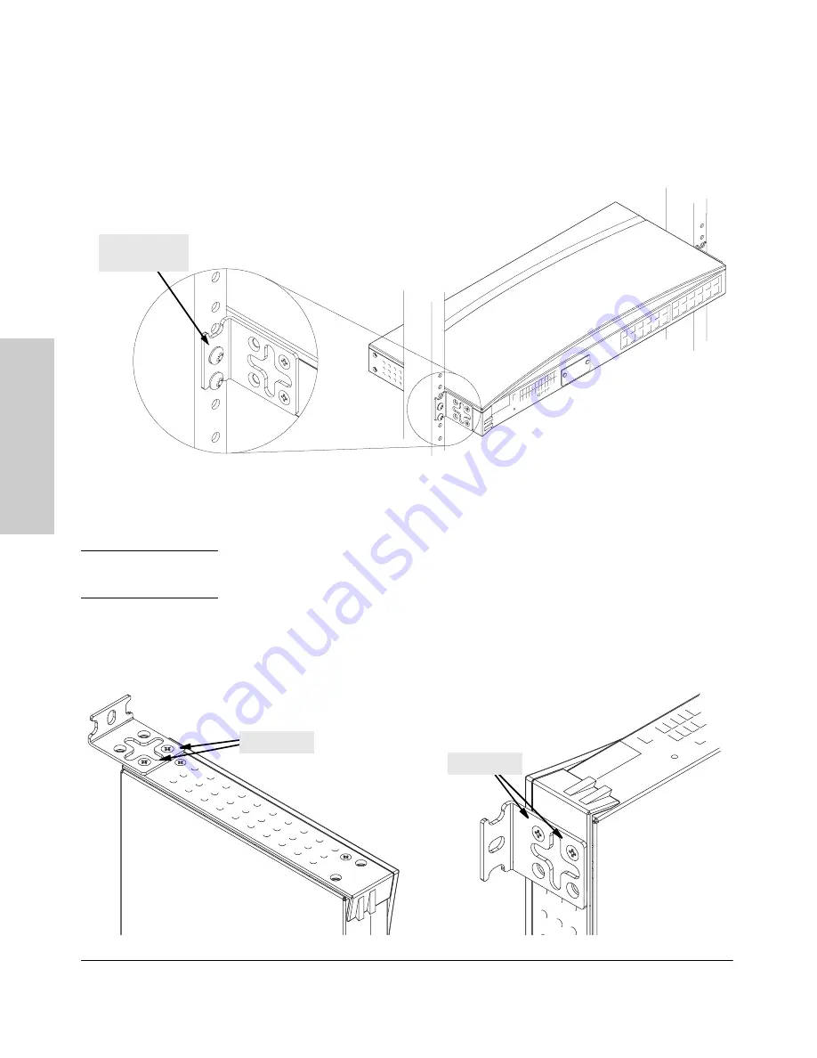
Install the other number 12-24 screw into the upper hole in each bracket. 
Tighten these screws.

Wall Mounting

You can mount the switch on a wall as shown in the illustrations below.

C a u t i o n

The switch should be mounted only to a wall or wood surface that is at least 
1/2-inch plywood or its equivalent.

1.

Use a #1 Phillips (cross-head) screwdriver and attach the mounting 
brackets to the switch with the included 8-mm M4 screws.

install additional 

screw

M4 screws

M4 screws

For “Bookshelf” Wall Mounting

For “Flat” Wall Mounting

Summary of Contents for J4868A

Page 1: ...hp procurve switch 2124 installation guide www hp com go hpprocurve ...

Page 2: ......

Page 3: ...HP Procurve Switch 2124 Installation Guide ...

Page 4: ...TO THE IMPLIED WARRANTIES OF MERCHANTABILITY AND FITNESS FOR A PARTICULAR PURPOSE Hewlett Packard shall not be liable for errors contained herein or for incidental or consequential damages in connection with the furnishing performance or use of this material Hewlett Packard assumes no responsibility for the use or reliability of its software on equipment that is not furnished by Hewlett Packard Wa...

Page 5: ...e Operation 1 6 2 Installing the Switch 2124 Included Parts 2 1 Installation Procedures 2 2 Summary 2 2 Installation Precautions 2 3 1 Prepare the Installation Site 2 4 2 Install An Optional Transceiver 2 5 3 Verify the Switch Operates Correctly 2 6 4 Mount the Switch 2 8 5 Connect the Switch to a Power Source 2 12 6 Connect the Network Cables 2 13 Example Network Topologies 2 14 As a Desktop Swit...

Page 6: ...A Specifications Physical A 1 Electrical A 1 Environmental A 1 Acoustic A 1 Connectors A 2 Safety A 2 B Switch Ports and Network Cables Switch Ports B 1 Cables B 2 Twisted Pair Cable Connector Pin Outs B 2 Straight Through Twisted Pair Cable for 10 Mbps or 100 Mbps Network Connections B 4 Crossover Twisted Pair Cable for 10 Mbps or 100 Mbps Network Connection B 5 C Safety and EMC Regulatory Statem...

Page 7: ...iated as the Switch 2124 The Switch 2124 has 24 auto sensing 10 100Base TX RJ 45 ports and a slot for installing an HP 100 FX SC Transceiver HP J4853A You can directly connect end node devices such as computers printers and servers to this switch providing dedicated bandwidth to those devices You can also connect this switch to hubs other switches or routers as part of your network infrastructure ...

Page 8: ...nnect any network devices to the switch One transceiver slot for installing the HP 100 FX SC Transceiver HP J4853A Reset Button This button is used to reset the switch while it is powered on This action executes the switch self test and may clear certain error conditions that have occurred Power LED Fault LED 10 100Base TX RJ 45 ports LED Mode Select button and indicator LEDs Reset button Slot for...

Page 9: ...nnected device Off One of these conditions exists no active network cable is connected to the port the port is not receiving link beat RJ 45 ports or sufficient light transceiver port for Port 25 transceiver port the transceiver has failed Blinking Port25only If the Port 25 Link LED is blinking simultaneously with the Fault LED it indicates that an unsupported transceiver has been installed in the...

Page 10: ...current setting is indicated by the Mode indicator LEDs near the button Press the button to change from one mode to the next If the Activity Act indicator LED is lit the Mode LED for each port displays activity information for the port it flickers as network traffic is received and transmitted through the port Ifthe Full Duplex FDx indicator LED is lit the Mode LEDs lightfor those ports that are o...

Page 11: ...r The Switch 2124 does not have a power switch it is powered on when connected to an active AC power source The switch automatically adjusts to any voltage between 100 240 volts and either 50 or 60 Hz There are no voltage range settings required AC power connector cooling vent make sure this is not obstructed for proper switch operation ...

Page 12: ...ted to the port it configures the port as MDI if the switch detects that an end node device is connected to the port it configures the port as MDI X automatic learning of the hardware addresses in the switch s 4000 entry address forwarding table automatically negotiated full duplex operation for the fixed 10 100 RJ 45 portswhen connectedtootherauto negotiating devices the transceiver port always o...

Page 13: ...connected to the switch does not use bandwidth dealing with unnecessary traffic flood whenever a new destination address is found in a packet received on a port the destination address will not yet be in the switch s address table and the Switch 2124 cannot know whether to forward or filter out the packet In this case it sends the packet to all the other switch ports This is referred to as floodin...

Page 14: ......

Page 15: ...you how to install your Switch 2124 Included Parts The Switch 2124 has the following components shipped with it HP Procurve Switch 2124 Installation Guide J4868 90001 this manual Customer Support Warranty booklet Accessory kit 5064 2085 two mounting brackets four 8 mm M4 screws to attach the mounting brackets to the switch four 5 8 inch number 12 24 screws to attach the switch to a rack four rubbe...

Page 16: ...ate the Switch 2124 it may be easier to install the transceiver first 3 Verify that the switch passes its self test This is a simple process of plugging the switch into a power source and observing that the LEDs on the switch s front panel show correct operation See page 2 7 4 Mount the switch The Switch 2124 can be mounted in a 19 inch telco rack or equipment cabinet on a wall or on a horizontal ...

Page 17: ...nes the regulations for power cords in your country The mark is your assurance that the power cord can be used safely with the switch When installing the switch note that the AC outlet should be near the switch and shouldbe easily accessible incase the switch mustbe powered off Ensure that the switch does not overload the power circuits wiring and over current protection To determine the possibili...

Page 18: ...Type Length Limits 10 100Base TX 10 Mbps operation Category 3 4 or 5 100 ohm differential unshieldedtwisted pair UTP orshielded twisted pair STP 100 Mbps operation Category 5 100 ohm differential UTP or STP 100 meters Note Since the 10Base T operation is through 10 100Base TX ports if you ever want to upgrade the ports to 100Base TX it would be best to cable the ports initially with category 5 cab...

Page 19: ...ng screws to secure the transceiver in place If you do not install a transceiver in the slot make sure that the slot cover plate is still attached over the slot for safe operation and proper switch cooling In the Switch 2124 the transceiver can operate only at full duplex Half duplex operation is not supported Installing a Transceiver Supported Transceiver Model Install only the HP J4853A 100 FX S...

Page 20: ...then into a nearby properly grounded electrical outlet N ot e The Switch 2124 does not have a power switch It is powered on when the power cord is connected to the switch and to a power source For safety the power outlet should be located near the switch installation The switch automatically adjusts to any voltage between 100 240 volts and either 50 or 60 Hz There are no voltage range settings req...

Page 21: ...e go into their normal operational mode If the ports are connected to active network devices the Link LEDs stay on and the Mode LEDs behave according to the mode selected In the default mode Activity the Mode LEDs should flicker showing network activity on the port If the ports are not connected to active network devices the Link and Mode LEDs will stay off If the LED display is different than wha...

Page 22: ...ent cabinet such as a server cabinet Wa r n i ng For safe operation please read the Installation Precautions on page 2 3 before mounting the switch Eq ui pm en t Ca bi ne t N ot e If you are installing the switch in an equipment cabinet use the clips and screws that came with the cabinet in place of the 12 24 screws that are supplied with the switch Plan which four holesyou will be using in the ca...

Page 23: ...and tighten the four screws holding the brackets to the rack 2 Partially install a screw 5 8 inch number 12 24 into the top hole of a pair of holes that are 0 5 inches apart in each rack cabinet upright as shown in the illustration below Ensure that the screws are at the same level in each upright 3 Place the switch in the rack and lower it so the notches in the bottom of the bracket slide onto th...

Page 24: ... mount the switch on a wall as shown in the illustrations below Ca ut ion The switch should be mounted only to a wall or wood surface that is at least 1 2 inch plywood or its equivalent 1 Use a 1 Phillips cross head screwdriver and attach the mounting brackets to the switch with the included 8 mm M4 screws installadditional screw M4 screws M4 screws For Bookshelf Wall Mounting For Flat Wall Mounti...

Page 25: ...res Installing the Switch 2124 2 Attach the switch to the wall or wood surface with 5 8 inch number 12 wood screws not included 5 8 inch wood screws 5 8 inch wood screw second 5 8 inch wood screw hidden For Bookshelf Wall Mounting For Flat Wall Mounting ...

Page 26: ...om of the switch within the embossed angled lines Use a sturdy surface in an uncluttered area You may want to secure the networking cables and switch power cord to the table leg or other part of the surface structure to help prevent tripping over the cords N ot e Make sure the air flowisnot restricted around the sides and back of the switch 5 Connect the Switch to a Power Source 1 Plug the include...

Page 27: ...bleshooting To disconnect Press the small tab on the plug and pull the plug out of the jack Connecting Cables to the HP 100 FX SC Transceiver If you have an HP 100 FX SC Transceiver installed in the switch see the documentation accompanying the transceiver for information on connecting fiber optic cables to the transceiver and for fiber optic cabling configurations The transceiver documentation al...

Page 28: ...o the switch by straight through or crossover twisted pair cables Either cable type can be used because of the HP Auto MDIX feature on the Switch 2124 N ot e The HP 100 FX SC Transceiver when installed in a Switch 2124 operates only at 100 Mbps and full duplex It cannot operate at half duplex The illustrations on the next two pages show fiber optic connections between the HP 100 FX SC Transceiver ...

Page 29: ...e switch and the hubs and between the switch and end nodes or servers can be through category 5 straight through or crossover twisted pair cable Category 3 or 4 cable can also be used if the connection is 10 Mbps only In all cases the device ports must be configured to auto negotiate the link characteristics for this feature to work The switch in turn is connected to a network backbone through fib...

Page 30: ...o form a larger switched network All the devices in this network can communicate with each other With a Gigabit SX Module for example installed in the Switch 8000M the entire switched topology could be connected to a campus backbone as shown in the illustration above N ot e For the 100Base FX connection between the Switch 2124 and the Switch 8000 to work properly be sure that the 100Base FX port o...

Page 31: ...atically negotiate both link speed and communication mode if the connected device has a fixed configuration for example 100 Mbps at half or full duplex the switch will automatically sense the link speed but will default to a communication of half duplex Because the Switch 2124 behaves in this way in compliance with the IEEE 802 3 standard if a device connected to the switch RJ 45 ports has a fixed...

Page 32: ...rtant to make sure you have a valid network topology Common topology faults include excessive cablelengthandexcessive repeaterdelaysbetweenendnodes Ifyouhave network problems after recent changes to the network change back to the previous topology If you no longer experience the problems the new topology is probably at fault Example topologies are shown at the end of chapter 2 in this book and som...

Page 33: ...Verify that the power cord is plugged into an active power source and to the switch Make sure these connections are secure 2 Try power cycling the switch by unplugging and plugging the power cord back in 3 If the Power LED is still not on verify that the AC power source works by plugging another device into the outlet Or try plugging the switch into a different outlet or try a different power cord...

Page 34: ...d to the transmit port on the connected device Verify that the connected devices comply with the IEEE 802 3 standard including transmission of the Link Beat signal See Testing Twisted Pair Cabling on page 3 5 Try the Testing End to End Network Communications procedures on page 3 6 If the other procedures don t resolve the problem try using a different port or a different cable For Port 25 transcei...

Page 35: ...ont of the switch goes off after approximately 3 seconds If thisLED stayson longer than 10 secondsor begins blinking an error condition has been detected on the switch See Diagnosing with the LEDs on page 3 3 for information on interpreting the LED patterns Testing Twisted Pair Cabling Network cables that fail to provide a link or provide an unreliable link between the switch and the connected net...

Page 36: ...two PCs is functioning correctly See your LAN adapter documentation for more information on running a link test or Ping test HP Customer Support Services Ifyouarestillhaving troublewithyourswitch Hewlett Packardofferssupport 24 hours a day seven days a week through the use of a number of automated electronic services See the Customer Support Warranty booklet that came with your switch for informat...

Page 37: ...se Emission LwA 40 dB in a virtual workspace according to DIN 45635 T 19 Width 44 2 cm 17 4 in Depth 20 5 cm 8 1 in Height 4 4 cm 1 7 in Weight 2 5 kg 5 5 lbs AC voltage 100 240 volts Maximum current 1 0 A Frequency range 50 60 Hz Operating Non Operating Temperature 0 C to 55 C 32 F to 131 F 40 C to 70 C 40 F to 158 F Relative humidity non condensing 15 to 95 at 40 C 104 F 15 to 90 at 65 C 149 F M...

Page 38: ...e with the IEEE 802 3u 100Base TX and IEEE 802 3 10Base T standards The 100 Mbps SC fiber optic porton the optional transceiver is compatible with the IEEE 802 3u 100Base FX standard Safety The Switch 2124 complies with these safety standards EN60950 IEC 950 CSA 22 2 No 950 NOM 019 SCFI 1994 UL 1950 ...

Page 39: ...ause of problems for LAN communications HP recommends that you work with a qualified LAN cable installer for assistance with your cabling requirements Switch Ports Twisted Pair The fixed RJ 45 10 100Base TX ports on the switch accept 100 ohm differ ential unshielded and shielded twisted pair cable with RJ 45 connectors as described on the next page Fiber Optic The SC type connector port on the HP ...

Page 40: ...e switch port operates as an MDI X port and connects correctly So for any connection a straight through twisted pair cable can be used you no longer have to use crossover cables If you do happen to use a correctly wired crossover cable though the switch will still be able to automatically detect the MDI MDI X operation of the connected device and will link correctly 10 Mbps Operation Category 3 4 ...

Page 41: ... TIA 568 B not USOC See the Pin Assignment tables below the cable illustrations later in this appendix for a listing of the signals used on each pin For 10 Mbps connections to the ports you can use 100 ohm differential Category 3 4 or 5 unshielded UTP or shielded STP twisted pair cable as supported by the IEEE 802 3 10Base T standard For 100 Mbps connections to the ports use 100 ohm differential C...

Page 42: ...ugh cables Cable Diagram N ot e Pins 1 and 2 on connector A must be wired as a twisted pair to pins 1 and 2 on connector B Pins 3 and 6 on connector A must be wired as a twisted pair to pins 3 and 6 on connector B Pins 4 5 7 and 8 are not used in this application although they may be wired in the cable Pin Assignments Straight Through Cable white orange orange white white green green white Connect...

Page 43: ...es Cable Diagram N ot e Pins 1 and 2 on connector A must be wired as a twisted pair to pins 3 and 6 on connector B Pins 3 and 6 on connector A must be wired as a twisted pair to pins 1 and 2 on connector B Pins 4 5 7 and 8 are not used in this application although they may be wired in the cable Pin Assignments Crossover Cable white orange orange white white green green white Connector A Connector ...

Page 44: ......

Page 45: ... to hazardous transient volt ages such aslightning or disturbancesin the electrical utilities power grid Handle exposed metal components ofthe networkwith caution Servicing There are no user serviceable parts inside these products Any servicing adjustment maintenance or repair mustbe performed only by service trained personnel These products do not have a power switch they are powered on when the ...

Page 46: ...tre soumis à des surtensions transitoires dangereuses telles que la foudre ou des perturba tions dans le réseau d alimentation public Manipulez les composants métalliques du réseau avec précautions Aucune pièce contenue à l intérieur de ce produit ne peut être réparée par l utilisateur Tout dépannage réglage entretien ou réparation devra être confié exclusivement à un personnel qualifié Cet appare...

Page 47: ...ungen aus gesetzt werden beispielsweise durch Blitz oder Störungen in dem Starkstromnetz des Elektrizitätswerks Bei der Handhabung exponierter Metallbestandteile des Netzwerkes Vorsicht walten lassen Dieses Gerät enthält innen keine durch den Benutzer zu wartenden Teile Wartungs Anpassungs Instandhaltungs oder Reparaturarbeiten dürfen nur von geschultem Bedienungspersonal durchgeführt werden Diese...

Page 48: ...i fra loro i cavi LAN possono occasionalmente andare soggetti a pericolose tensioni transitorie ad esempio provocate da lampi o disturbi nella griglia d alimen tazione della società elettrica siate cauti nel toccare parti esposte in metallo della rete Nessun componente di questo prodotto può essere riparato dall utente Qualsiasi lavoro di riparazione messa a punto manutenzione o assistenza va effe...

Page 49: ... modo seguro Es posible que los cables de la LAN se vean sometidos de vez en cuando a voltajes momentáneos que entrañen peligro rayos o alteraciones en la red de energía eléctrica Manejar con precaución los componentes de metal de la LAN que estén al descubierto Este aparato no contiene pieza alguna susceptible de reparación por parte del usuario Todas las reparaciones ajustes o servicio de manten...

Page 50: ...C 6 Safety and EMC Regulatory Statements Safety Information Japan Safety and EMC Regulatory Statements Safety Information Japan ...

Page 51: ...C 7 Safety and EMC Regulatory Statements Safety Information China Safety and EMC Regulatory Statements Safety Information China ...

Page 52: ...ment is operated in a commercial environment This equipment gener ates uses and can radiate radio frequency energy and if not installed and used in accordance with the instruction manual may cause interference to radio communications Operation of this equipment in a residential area may cause interference in which case the user will be required to correct the interference at his own expense Canada...

Page 53: ...C 9 Safety and EMC Regulatory Statements EMC Regulatory Statements Safety and EMC Regulatory Statements Korea Taiwan ...

Page 54: ...C 10 Safety and EMC Regulatory Statements EMC Regulatory Statements Safety and EMC Regulatory Statements European Community ...

Page 55: ...bles 100Base FX connections 2 4 100Base TX connections 2 4 10Base T connections 2 4 connecting cables to switch ports 2 13 effects of non standard cables 3 2 infrastructure requirements 2 4 twisted pair connector pin outs B 2 cables twisted pair crossover cable pin out B 5 MDI X to MDI connections B 4 MDI X to MDI X connections B 5 straight through cable pin out B 4 switch to computer connection B...

Page 56: ...de Select button 1 4 indicator LEDs 1 3 LEDs behavior during self test 2 7 blinking definition 1 3 checking during troubleshooting 3 5 descriptions of 1 3 error indications 3 3 Fault 1 3 showing error conditions 3 3 Link 1 3 location on switch 1 2 Mode description 1 3 selecting the display 1 4 mode select indicators 1 3 on switch 1 3 Power 1 3 behavior during self test 2 7 length limitations 100Ba...

Page 57: ...s C 1 safety specifications A 2 segment switch example topology 2 15 selecting the Mode LED display 1 4 self test LED behavior during 2 7 slot for transceiver module location on switch 1 2 specifications connectors A 2 electrical A 1 environmental A 1 physical A 1 safety A 2 straight through cable pin out B 4 summary of switch installation 2 2 switch connecting to a power source 2 12 description 1...

Page 58: ... network problems 3 1 diagnostic tests 3 5 effects of improper topology 3 2 effects of non standard cables 3 2 testing end to end communications 3 6 testing the switch 3 5 testing the twisted pair cables 3 5 twisted pair cable crossover cable pin out B 5 pin outs B 2 straight through cable pin out B 4 switch to computer connection B 4 switch to switch or hub connection B 5 testing 3 5 W wall mount...

Page 59: ......

Page 60: ...t notice Copyright Hewlett Packard Company 2001 All rights reserved Reproduction adaptation or translation without prior written permission is prohibited except as allowed under the copyright laws Printed in Taiwan June 2001 Manual Part Number J4868 90001 J4868 90001 ...

Reviews: