background image

TouchPad button board

Description

Spare part number

TouchPad button board

821668-001

TouchPad button board w/NFC antenna

821667-001

Before removing the TouchPad button board, follow these steps:

1.

Shut down the computer. If you are unsure whether the computer is off or in Hibernation, turn 
the computer on, and then shut it down through the operating system.

2.

Disconnect all external devices connected to the computer.

3.

Disconnect the power from the computer by first unscrewing the power cord from the AC outlet, and 
then unscrewing the AC adapter from the computer.

4.

Remove the bottom cover (see 

Bottom cover on page 33

).

5.

Remove the battery (see 

Battery on page 36

).

6.

Remove the system board (see 

System board on page 49

).

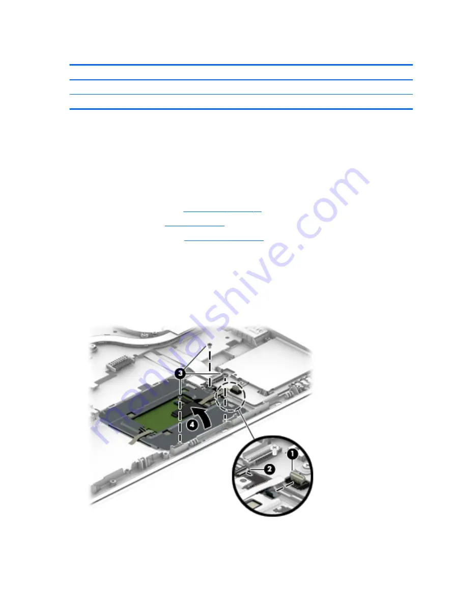
Remove the TouchPad button board:

1.

Disconnect the cable from the TouchPad to the smart card reader board (1), and then disconnect the NFC 
antenna from the NFC module (2).

2.

Lift the tape, and then remove the 3 Phillips PM2.5×3.0 screws (3) that secure the TouchPad button 
board to the top cover.

3.

Lift the bottom of the TouchPad button board up, and then pull it forward to remove it from the slot (4).

Reverse this procedure to install the TouchPad board.

56

Chapter 6   Removal and replacement procedures for Authorized Service Provider parts

Summary of Contents for EliteBook 725 G4

Page 1: ...HP EliteBook 725 G4 Notebook PC Maintenance and Service Guide ...

Page 2: ...Studio Sound is a trademark of DTS Inc DTS Inc All Rights Reserved Product notice This guide describes features that are common to most models Some features may not be available on your computer Not all features are available in all editions of Windows 10 or Windows 8 This computer may require upgraded and or separately purchased hardware drivers and or software to take full advantage of Windows 1...

Page 3: ...hat should only be accessed by an authorized service provider See Chapter 5 Removal and replacement procedures for Customer Self Repair parts for details Accessing parts described in Chapter 6 Removal and replacement procedures for Authorized Service Provider only parts can damage the computer or void your warranty iii ...

Page 4: ...iv Important Notice about Customer Self Repair Parts ...

Page 5: ...w another hard surface such as an adjoining optional printer or a soft surface such as pillows or rugs or clothing to block airflow Also do not allow the AC adapter to contact the skin or a soft surface such as pillows or rugs or clothing during operation The device and the AC adapter comply with the user accessible surface temperature limits defined by the International Standard for Safety of Inf...

Page 6: ...vi Safety warning notice ...

Page 7: ...uter major components 17 Display assembly subcomponents 22 Plastics Kit 23 Cable Kit 24 Mass storage devices 25 Miscellaneous parts 26 4 Removal and replacement procedures preliminary requirements 28 Tools required 28 Service considerations 28 Plastic parts 28 Cables and connectors 29 Drive handling 29 Grounding guidelines 30 Electrostatic discharge damage 30 Packaging and transporting guidelines ...

Page 8: ...mart card reader board 58 Speaker assembly 59 Display assembly 59 7 Computer Setup BIOS TPM and HP Sure Start in Windows 10 66 Using Computer Setup 66 Starting Computer Setup 66 Navigating and selecting in Computer Setup 66 Restoring factory settings in Computer Setup 67 Updating the BIOS 68 Determining the BIOS version 68 Downloading a BIOS update 68 Changing the boot order using the f9 prompt 69...

Page 9: ...ery media to recover 76 Changing the computer boot order 77 Removing the HP Recovery partition select products only 78 10 Specifications 79 Input power 79 Operating environment 79 11 Power cord set requirements 80 Requirements for all countries 80 Requirements for specific countries and regions 80 12 Statement of memory volatility 82 Nonvolatile memory usage 84 Questions and answers 86 Using HP Su...

Page 10: ...x ...

Page 11: ...s equipped with an AMD A12 Pro 9800B or AMD A12 Pro 8830B processor AMD Radeon R5 only on computer models equipped with an AMD A10 Pro 8730B or AMD A8 Pro 9600B processor Panel 12 5 in 31 75 cm high definition HD Slim eDP 1366 768 SVA AG typical brightness 220 cd m2 nits with and without webcam 12 5 in 31 75 cm full high definition FHD UltraSlim eDP 1920x1080 UWVA AG typical brightness 300 cd m2 n...

Page 12: ...tions by way of wireless module Two WLAN antennas built into display assembly Integrated wireless personal area network PAN supported by Bluetooth 4 0 or Bluetooth 4 2 combo card Compatible with Miracast certified devices Support for the following WLAN formats Intel Dual Band Wireless AC 7265 802 11 AC 2 2 WiFi Bluetooth 4 2 Combo Adapter non vPro Intel Dual Band Wireless AC 3168 802 11 AC 1 1 WiF...

Page 13: ...9 WHr 4 25 AHr Li ion battery 65 W HP Smart AC adapter 45 W HP Smart AC adapter 45 W 2 prong AC adapter Security Security lock Fingerprint reader Supports Trusted Platform Module TPM 1 2 or 2 0 Infineon soldered down Integrated Smart Card reader active Preboot authentication password smart card Operating system Preinstalled Windows 10 Home 64 bit not available on computer models equipped with an F...

Page 14: ...8 GB or more system memory Windows 10 Professional 64 bit Downgrade Windows 7 64 bit StF MSNA Standard not available on computer models equipped with an FHD or higher resolution display assembly and 8 GB or more system memory Windows 10 Professional 64 bit Downgrade Windows 7 64 bit Volume License Windows 7 Home Basic 64 bit CPPP only available on computer models with country loc PRC Windows 7 Pro...

Page 15: ...tion Operating system continued Web only support Windows 7 Professional 64 bit Serviceability End user replaceable parts AC adapter Battery Hard drive Keyboard Memory module Solid state drive WLAN module WWAN module 5 ...

Page 16: ... powered stereo speakers headphones earbuds a headset or a television audio cable Also connects an optional headset microphone This jack does not support optional microphone only devices WARNING To reduce the risk of personal injury adjust the volume before putting on headphones earbuds or a headset For additional safety information refer to the Regulatory Safety and Environmental Notices To acces...

Page 17: ...Component Description 7 Docking connector Connects an optional docking device 8 SIM card slot Supports a wireless subscriber identity module SIM card 9 Power connector Connects an AC adapter Right 7 ...

Page 18: ... to cycle on and off during routine operation 3 External monitor port Connects an external VGA monitor or projector 4 USB 3 1 charging powered port Connects an optional USB device such as a keyboard mouse external drive printer scanner or USB hub Standard USB ports will not charge all USB devices or will charge using a low current Some USB devices require power and require you to use a powered por...

Page 19: ...s allow you to video conference and chat online using streaming video To use the webcam Type camera in the taskbar search box and then select Camera The antennas are not visible from the outside of the computer For optimal transmission keep the areas immediately around the antennas free from obstructions For wireless regulatory notices see the section of the Regulatory Safety and Environmental Not...

Page 20: ...ht Turns the TouchPad on and off On The TouchPad is off Off The TouchPad is on 4 TouchPad zone Reads your finger gestures to move the pointer or activate items on the screen 5 Left TouchPad button Functions like the left button on an external mouse 6 Right pointing stick button select products only Functions like the right button on an external mouse 7 Right TouchPad button Functions like the righ...

Page 21: ...er is off or in Hibernation Hibernation is a power saving state that uses the least amount of power 3 Volume mute light Amber Computer sound is off Off Computer sound is on 4 Microphone mute light Amber microphone sound is off Off microphone sound is on 5 Wireless light On An integrated wireless device such as a wireless local area network WLAN device and or a Bluetooth device is on NOTE On some m...

Page 22: ... the power button results in the loss of unsaved information If the computer has stopped responding and shutdown procedures are ineffective press and hold the power button for at least 15 seconds to turn off the computer To learn more about your power settings see your power options Type power in the taskbar search box and then select Power and sleep settings or Right click the Start button and th...

Page 23: ... lock key or the esc key 3 Windows key Opens the Start menu NOTE Pressing the Windows key again will close the Start menu 4 Embedded numeric keypad A numeric keypad superimposed over the keyboard alphabet keys that enables you to add subtract and perform other numeric tasks When num lock is on the keypad can be used like an external numeric keypad 5 num lock key Turns the embedded numeric keypad o...

Page 24: ...vice 2 Vents 2 Enable airflow to cool internal components NOTE The computer fan starts up automatically to cool internal components and prevent overheating It is normal for the internal fan to cycle on and off during routine operation 14 Chapter 2 External component identification ...

Page 25: ...off or in Hibernation Hibernation is a power saving state that uses the least amount of power 3 Battery light When AC power is connected White The battery charge is greater than 90 percent Amber The battery charge is from 0 to 90 percent Off The battery is not charging When AC power is disconnected battery not charging Blinking amber The battery has reached a low battery level When the battery has...

Page 26: ...mputer This information may be needed when travelling internationally or when contacting support 1 Serial number 2 Product number 3 Model number 4 Warranty period Using Windows briefly press the fn esc key combination to display the System Information screen which provides the product name and serial number of your computer as well as information about the memory processor BIOS and keyboard 16 Cha...

Page 27: ...ter See Service label on page 16 for details Item Component Spare part number 1 12 5 in FHD 1920 1080 ultraslim eDP UWVA TouchScreen display assembly 920050 001 NOTE Non TouchScreen display assemblies are spared at the subcomponent level only For non TouchScreen display assembly spare part information see Display assembly subcomponents on page 22 2 Keyboard with backlight and pointing stick includ...

Page 28: ...Africa 826630 FP1 For use in Norway 826630 091 For use in Portugal 826630 131 For use in Romania 826630 271 For use in Russia 826630 251 For use in Saudi Arabia 826630 171 For use in Slovenia 826630 BA1 For use in South Korea 826630 AD1 For use in Spain 826630 071 For use in Sweden and Finland 826630 B71 For use in Switzerland 826630 BG1 For use in Taiwan 826630 AB1 For use in Thailand 826630 281 ...

Page 29: ...merica 826631 161 For use in the Netherlands 826631 B31 For use in Northwest Africa 826631 FP1 For use in Norway 826631 091 For use in Portugal 826631 131 For use in Romania 826631 271 For use in Russia 826631 251 For use in Saudi Arabia 826631 171 For use in South Korea 826631 AD1 For use in Slovenia 826631 BA1 For use in Spain 826631 071 For use in Sweden and Finland 826631 B71 For use in Switze...

Page 30: ...7265 802 11 AC 2 2 WiFi Bluetooth 4 2 Combo Adapter non vPro 860883 001 9 WWAN module HP hs3210 WW HSPA 860726 001 HP It4132 LTE HSPA with GPS M 2 WWAN module 845710 001 HP It4120 LTE EVDO HSPA with GPS M 2 800870 001 10 Solid state drive 512 GB Turbo Drive G2 TLC 915943 001 360 GB PCIe TLC 915941 001 256 GB Turbo Drive G2 TLC 915939 001 256 GB SATA 3 SED OPAL TLC 915940 001 128 GB M 2 SATA 3 9159...

Page 31: ...ith an AMD A10 8730B processor and the Windows 10 operating system 911739 601 Equipped with an AMD A10 8730B processor and a non Windows operating system 911739 001 Equipped with an AMD A8 9600B processor and the Windows 10 operating system 911737 601 Equipped with an AMD A8 9600B processor and a non Windows operating system 911737 001 17 RTC battery includes cable and double sided adhesive 702853...

Page 32: ...bezel 821658 001 2 Microphone module includes cable 920579 001 3 Webcam module includes cable 800575 020 4 Display panel 12 5 in FHD 1920 1080 slim eDP UWVA AG 50 WLED non TouchScreen display panel typical brightness 300 nits 832199 005 22 Chapter 3 Illustrated parts catalog ...

Page 33: ...74 001 8 WWAN antenna includes wireless antenna cables and transceivers included in the display back cover spare part kit 9 WLAN antenna includes wireless antenna cables and transceivers included in the display back cover spare part kit 10 Back cover includes wireless antenna cables and transceivers 862350 001 Plastics Kit Item Component Spare part number Plastics Kit 821675 001 1 Fingerprint read...

Page 34: ...Cable Kit Item Component Spare part number Cable Kit 912091 001 1 NFC module cable 2 Pointing stick cable 3 Display panel cable 24 Chapter 3 Illustrated parts catalog ...

Page 35: ...72 001 500 GB 7200 rpm 7 0 mm SED 820573 001 2 Hard Drive Hardware Kit includes hard drive connector cable hard drive rubber bracket and screws 821665 001 3 Solid state drive 512 GB Turbo Drive G2 TLC 915943 001 360 GB PCIe TLC 915941 001 256 GB Turbo Drive G2 TLC 915939 001 256 GB SATA 3 SED OPAL TLC 915940 001 128 GB M 2 SATA 3 915938 001 Mass storage devices 25 ...

Page 36: ...g station cable lock 575921 001x HP Elite USB C docking station 844550 001x HP Essential backpack 679921 001x HP Essential top load case 679923 001 HP external DVD RW DL SuperMulti Drive 747080 001 HP HDMI to VGA adapter 701943 001 HP Mobile Connect 714749 001 HP slim Ultrabook top load case 747078 001x HP Smart AC adapter dongle 7 4 mm 734734 001x HP Ultraslim keyed cable lock 703372 001x HP USB ...

Page 37: ...Europe 213350 009 For use in India 404827 003 For use in Israel 398063 003 For use in Italy 213352 008 For use in Japan 349756 002 For use in North America 213349 009 For use in the People s Republic of China 286497 008 For use in South Korea 267836 008 For use in Switzerland 213354 008 For use in Taiwan 393313 003 For use in Thailand 285096 006 For use in the United Kingdom and Singapore 213351 0...

Page 38: ...ing sections include some of the considerations that you must keep in mind during disassembly and assembly procedures NOTE As you remove each subassembly from the computer place the subassembly and all accompanying screws away from the work area to prevent damage Plastic parts CAUTION Using excessive force during disassembly and reassembly can damage plastic parts Use care when handling the plasti...

Page 39: ...nserting a hard drive shut down the computer If you are unsure whether the computer is off or in Hibernation turn the computer on and then shut it down through the operating system Before handling a drive be sure that you are discharged of static electricity While handling a drive avoid touching the connector Before removing a diskette drive or optical drive be sure that a diskette or disc is not ...

Page 40: ... components in their electrostatic safe containers until you are ready to install them Before touching an electronic component discharge static electricity by using the guidelines described in this section Avoid touching pins leads and circuitry Handle electronic components as little as possible If you remove a component place it in an electrostatic safe container The following table shows how hum...

Page 41: ... to ground and that proper materials are selected to avoid static charging When grounding is not possible use an ionizer to dissipate electric charges Workstation guidelines Follow these grounding workstation guidelines Cover the workstation with approved static shielding material Use a wrist strap connected to a properly grounded work surface and use properly grounded tools and equipment Use cond...

Page 42: ...operator and ground To be effective the conductive must be worn in contact with the skin The following grounding equipment is recommended to prevent electrostatic damage Antistatic tape Antistatic smocks aprons and sleeve protectors Conductive bins and other assembly or soldering aids Nonconductive foam Conductive tabletop workstations with ground cords of one megohm resistance Static dissipative ...

Page 43: ...r your computer go to http partsurfer hp com select your country or region and then follow the on screen instructions There are as many as 20 screws that must be removed replaced and or loosened when servicing Customer Self Repair parts Make special note of each screw size and location during removal and replacement Bottom cover Description Spare part number Bottom cover 821662 001 Before removing...

Page 44: ...as shown in the following image The rubber screw covers should be installed in the locations indicated in the following image The rubber screw covers are included in the Plastics Kit spare part number 821675 001 34 Chapter 5 Removal and replacement procedures for Customer Self Repair parts ...

Page 45: ...cated in the following image 5 Remove the PM2 0 7 0 screw 1 in the SD card slot that secures the bottom cover to the computer 6 Use a case utility tool to release the rear edge 2 of the bottom cover 7 Remove the bottom cover 3 Reverse the removal procedures to install the bottom cover Component replacement procedures 35 ...

Page 46: ...er on page 33 To remove the battery WARNING To reduce potential safety issues use only the user replaceable battery provided with the computer a replacement battery provided by HP or a compatible battery purchased from HP CAUTION Removing a user replaceable battery that is the sole power source for the computer can cause loss of information To prevent loss of information save your work or shut dow...

Page 47: ...hrough the operating system 2 Disconnect all external devices connected to the computer 3 Disconnect the power from the computer by first unscrewing the power cord from the AC outlet and then unscrewing the AC adapter from the computer 4 Remove the bottom cover see Bottom cover on page 33 5 Remove the battery see Battery on page 36 To remove the hard drive 1 Loosen the 4 captive screws 1 that secu...

Page 48: ...e removing the solid state drive follow these steps 1 Turn off the computer If you are unsure whether the computer is off or in Hibernation turn the computer on and then shut it down through the operating system 2 Disconnect the power from the computer by first unscrewing the power cord from the AC outlet and then unscrewing the AC adapter from the computer 3 Disconnect all external devices from t...

Page 49: ...orrect insertion Reverse this procedure to reassemble and install the mSATA drive NOTE Only a hard drive or an solid state drive can be installed To install an solid state drive be sure that the standee is in place across from the connector and not stored beside the hard drive slot Component replacement procedures 39 ...

Page 50: ...l 5 Select the operating system and then click Next 6 Under Step 2 Select a Download click the BIOS link 7 Click the link for the most recent BIOS 8 Click the Download button and then follow the on screen instructions Before removing the memory module follow these steps 1 Shut down the computer If you are unsure whether the computer is off or in Hibernation turn the computer on and then shut it do...

Page 51: ...orrect insertion into the memory module slot NOTE The computer uses two memory sockets The socket labeled 2 houses the expansion memory module and the socket labeled 1 houses the primary memory module The removal procedure is the same for both memory sockets Reverse this procedure to install a memory module Component replacement procedures 41 ...

Page 52: ...wing the power cord from the AC outlet and then unscrewing the AC adapter from the computer 4 Remove the bottom cover see Bottom cover on page 33 5 Remove the battery see Battery on page 36 Remove the WLAN module 1 Disconnect the WLAN antenna cables 1 from the terminals on the WLAN module NOTE The WLAN antenna cable labeled 1 connects to the WLAN module Main terminal labeled 1 The WLAN antenna cab...

Page 53: ...ith a notch to prevent incorrect insertion NOTE If the WLAN antennas are not connected to the terminals on the WLAN module the protective sleeves must be installed on the antenna connectors as shown in the following illustration Reverse this procedure to install the WLAN module Component replacement procedures 43 ...

Page 54: ...nect the power from the computer by first unscrewing the power cord from the AC outlet and then unscrewing the AC adapter from the computer 4 Remove the bottom cover see Bottom cover on page 33 5 Remove the battery see Battery on page 36 Remove the WWAN module 1 Position the computer upside down 2 Disconnect the WWAN antenna cables 1 from the terminals on the WWAN module NOTE The red WWAN antenna ...

Page 55: ...ith a notch to prevent incorrect insertion NOTE If the WWAN antennas are not connected to the terminals on the WWAN module the protective sleeves must be installed on the antenna connectors as shown in the following illustration Reverse this procedure to install the WWAN module Component replacement procedures 45 ...

Page 56: ...630 031 For use in Hungary 826630 211 For use in Russia 826630 251 For use in the United States 826630 001 For use in Iceland 826630 DD1 Keyboard with backlight and pointing stick includes backlight cable keyboard cable and pointing stick cable For use in Saudi Arabia 826631 171 For use in Belgium 826631 A41 For use in India 826631 D61 For use in Slovenia 826631 BA1 For use in Brazil 826631 201 Fo...

Page 57: ...mputer 1 2 Position the computer upright with the front toward you 3 Open the computer as far as possible 4 Insert a screwdriver or similar thin tool into the hole beside the heat sink fan assembly and then press on the back of the keyboard until it disengages from the computer 2 Rotate the top of the keyboard upward and then lift the keyboard up at an angle to disengage the tabs at the bottom of ...

Page 58: ...6 Remove the keyboard 5 Reverse this procedure to install the keyboard 48 Chapter 5 Removal and replacement procedures for Customer Self Repair parts ...

Page 59: ... or region and then follow the on screen instructions There are as many as 29 screws that must be removed replaced and or loosened when servicing Authorized Service Provider only parts Make special note of each screw size and location during removal and replacement System board NOTE All system board spare part kits include an AMD processor and replacement thermal material Description Spare part nu...

Page 60: ...yboard on page 46 b Hard drive see Hard drive on page 37 c solid state drive see Solid state drive on page 38 When replacing the system board be sure to remove the following components from the defective system board and install on the replacement system board Memory modules see Memory modules on page 40 WLAN Bluetooth module see WLAN module on page 42 WWAN module see WWAN module on page 44 RTC ba...

Page 61: ...e system board to the computer 3 Lift the right side of the system board 2 until it rests at an angle 4 Remove the system board 3 by sliding it up and to the right at an angle Reverse this procedure to install the system board Component replacement procedures 51 ...

Page 62: ...uter 3 Disconnect the power from the computer by first unscrewing the power cord from the AC outlet and then unscrewing the AC adapter from the computer 4 Remove the bottom cover see Bottom cover on page 33 5 Remove the battery see Battery on page 36 6 Remove the system board see System board on page 49 Remove the RTC battery 1 Remove the RTC battery cable from the system board 1 2 Using a flat to...

Page 63: ... see Bottom cover on page 33 5 Remove the battery see Battery on page 36 6 Remove the system board see System board on page 49 Remove the heat sink fan assembly Disconnect the fan cable 1 loosen the six captive screws on the fan and heat sink following the sequence stamped on the heat sink 2 and then remove the heat sink fan assembly from the system board 3 CAUTION Take extreme care when removing ...

Page 64: ...Reverse this procedure to install the heat sink fan assembly 54 Chapter 6 Removal and replacement procedures for Authorized Service Provider parts ...

Page 65: ...ing the power cord from the AC outlet and then unscrewing the AC adapter from the computer 4 Remove the bottom cover see Bottom cover on page 33 5 Remove the battery see Battery on page 36 6 Remove the system board see System board on page 49 Remove the fingerprint reader assembly 1 Remove the Phillips PM2 5x3 0 screw 1 that secures the bracket to the top cover 2 Slide the bracket right and then l...

Page 66: ...screwing the AC adapter from the computer 4 Remove the bottom cover see Bottom cover on page 33 5 Remove the battery see Battery on page 36 6 Remove the system board see System board on page 49 Remove the TouchPad button board 1 Disconnect the cable from the TouchPad to the smart card reader board 1 and then disconnect the NFC antenna from the NFC module 2 2 Lift the tape and then remove the 3 Phi...

Page 67: ...en unscrewing the AC adapter from the computer 3 Disconnect all external devices from the computer 4 Remove the bottom cover see Bottom cover on page 33 5 Remove the battery see Battery on page 36 6 Remove the system board see System board on page 49 Remove the NFC module 1 Disconnect the system board cable 1 and the NFC antenna from the NFC module 2 Pry the NFC module from the smart card reader a...

Page 68: ...uter 4 Remove the bottom cover see Bottom cover on page 33 5 Remove the battery see Battery on page 36 6 Remove the system board see System board on page 49 Remove the smart card reader board NOTE Before you remove the smart card reader make sure nothing memory card or plastic insert in installed 1 Disconnect the cable from the board 1 2 Disconnect the cable from the TouchPad 2 3 Remove the 3 Phil...

Page 69: ...nscrewing the AC adapter from the computer 3 Disconnect all external devices from the computer 4 Remove the bottom cover see Bottom cover on page 33 5 Remove the battery see Battery on page 36 6 Remove the system board see System board on page 49 Remove the speaker assembly 1 Remove the two Phillips PM2 5x3 0 screws that secure the speakers to the computer 1 2 Remove the speaker 2 from the compute...

Page 70: ...o the computer 3 Disconnect the power from the computer by first unscrewing the power cord from the AC outlet and then unscrewing the AC adapter from the computer 4 Remove the bottom cover see Bottom cover on page 33 5 Remove the battery see Battery on page 36 Remove the display assembly 1 Position the computer upside down 2 Disconnect the display cable from the system board 60 Chapter 6 Removal a...

Page 71: ...route the antennas can result in degradation of the computer s wireless performance 4 Remove the 4 Phillips PM2 5 5 0 screws 1 that secure the display assembly to the computer 5 Swing the hinges 2 up and back 6 Slide the keyboard top cover 3 up and forward at and angle and separate the keyboard top cover from the display assembly NOTE The following steps apply only to computer models equipped with...

Page 72: ...on in following image when you remove the bezel b Remove the display bezel 4 The display bezel is available using spare part number 821658 001 8 If it is necessary to replace the webcam module or microphone module a Remove the display bezel b Detach the module 1 from the display back cover The module is attached to the display back cover with double sided adhesive c Disconnect the module cable 2 f...

Page 73: ...lips PM2 0 3 0 screws that secure the display panel to the display back cover CAUTION Before turning the display panel upside down make sure the work surface is clear of tools screws and any other foreign objects Failure to follow this caution can result in damage to the display panel c Lift the top edge of the display panel 1 and swing it up and forward until it rests upside down in front of the ...

Page 74: ...D display panels 10 If it is necessary to replace the display hinges a Remove the display bezel b Remove the display panel c Remove the two Phillips PM2 0 3 0 screws 1 that secure the hinge covers to the display back cover d Remove the hinge covers 2 The hinge covers are included in the Plastics Kit spare part number 821675 001 e Remove the six Phillips PM2 5 2 5 broad head screws 3 that secure th...

Page 75: ...play panel c Remove the display hinges d Release the display panel cable from the routing channel 1 and clips built into the top left and bottom edges of the display back cover e Remove the display panel cable 2 The display panel cable is included in the Cable Kit spare part number 912091 001 Reverse this procedure to reassemble and install the display assembly Component replacement procedures 65 ...

Page 76: ...etup Computers or tablets with keyboards Turn on or restart the computer and when the HP logo appears press f10 to enter Computer Setup Tablets without keyboards Turn off the tablet Press the power button in combination with the volume down button until the Startup menu is displayed and then tap F10 to enter Computer Setup Navigating and selecting in Computer Setup To select a menu or a menu item ...

Page 77: ...OTE Restoring defaults will not change the hard drive mode To return all settings in Computer Setup to the values that were set at the factory follow these steps 1 Start Computer Setup See Starting Computer Setup on page 66 2 Select Main and then select Apply Factory Defaults and Exit NOTE On select products the selections may display Restore Defaults instead of Apply Factory Defaults and Exit 3 F...

Page 78: ...omputer is connected to reliable external power using the AC adapter Do not download or install a BIOS update while the computer is running on battery power docked in an optional docking device or connected to an optional power source During the download and installation follow these instructions Do not disconnect power on the computer by unplugging the power cord from the AC outlet Do not shut do...

Page 79: ... on or restart the computer and when the HP logo appears press f9 to enter the Boot Device Options menu Tablets without keyboards Turn off the tablet Press the power button in combination with the volume down button until the Startup menu is displayed and then tap F9 to enter the Boot Device Options menu 2 Select a boot device then press enter TPM BIOS settings select products only IMPORTANT Befor...

Page 80: ... to its previously safe state without user intervention HP Sure Start is configured and already enabled so that most users can use the HP Sure Start default configuration The default configuration can be customized by advanced users To access the latest documentation on HP Sure Start go to http www hp com support and select your country Select Drivers Downloads and then follow the on screen instru...

Page 81: ...and create the HP UEFI support environment because only exe files are offered 2 Press or tap f2 The BIOS searches three places for the diagnostic tools in the following order a Connected USB drive NOTE To download the HP PC Hardware Diagnostics UEFI tool to a USB drive see Downloading HP PC Hardware Diagnostics UEFI to a USB device on page 71 b Hard drive c BIOS 3 When the diagnostic tool opens se...

Page 82: ...Drivers Downloads 3 In the text box enter the product name and then click Go or Click Find Now to let HP automatically detect your product 4 Select your computer and then select your operating system 5 In the Diagnostic section follow the on screen instructions to select and download the UEFI version you want 72 Chapter 8 HP PC Hardware Diagnostics UEFI ...

Page 83: ... the HP Recovery partition on the computer The backup can be used to reinstall the original operating system in cases where the hard drive is corrupted or has been replaced For information on creating recovery media see Creating HP Recovery media select products only on page 73 For information on the recovery options that are available using the recovery media see Using Windows tools on page 74 Us...

Page 84: ...rately to create recovery discs If you use an external optical drive it must be connected directly to a USB port on the computer the drive cannot be connected to a USB port on an external device such as a USB hub If you cannot create DVD media yourself you can obtain recovery discs for your computer from HP See the Worldwide Telephone Numbers booklet included with the computer You can also find co...

Page 85: ...o remove the recovery partition to reclaim hard drive space HP Recovery Manager offers the Remove Recovery Partition option For more information see Removing the HP Recovery partition select products only on page 78 Recovering using HP Recovery Manager HP Recovery Manager software allows you to recover the computer to its original factory state by using the HP Recovery media that you either create...

Page 86: ...rking To start HP Recovery Manager from the HP Recovery partition IMPORTANT For a tablet with a detachable keyboard connect the keyboard to the keyboard dock before beginning these steps select products only 1 Type recovery in the taskbar search box select Recovery Manager and then select HP Recovery Environment or For computers or tablets with keyboards attached press f11 while the computer boots...

Page 87: ...to the keyboard dock before beginning these steps 1 Insert the HP Recovery media 2 Access BIOS For computers or tablets with keyboards attached Turn on or restart the computer or tablet quickly press esc and then press f9 for boot options For tablets without keyboards Turn on or restart the tablet and then quickly hold down the volume down button then select f9 or Turn on or restart the tablet and...

Page 88: ...very partition So before you remove the Recovery partition create HP Recovery media see Creating HP Recovery media select products only on page 73 NOTE The Remove Recovery Partition option is only available on products that support this function Follow these steps to remove the HP Recovery partition 1 Type recovery in the taskbar search box and then select HP Recovery Manager 2 Select Remove Recov...

Page 89: ...within the following specifications Input Power Rating Operating voltage and current 19 5 V dc 2 31 A 45 W 19 5 V dc 3 33 A 65 W NOTE This product is designed for IT power systems in Norway with phase to phase voltage not exceeding 240 V rms NOTE The computer operating voltage and current can be found on the system regulatory label Operating environment Factor Metric U S Temperature Operating writ...

Page 90: ...st be approved by an acceptable accredited agency responsible for evaluation in the country or region where the power cord set will be used The power cord sets must have a minimum current capacity of 10 amps and a nominal voltage rating of 125 or 250 V AC as required by the power system of each country or region The appliance coupler must meet the mechanical configuration of an EN 60 320 IEC 320 S...

Page 91: ...wall plug must bear a T mark and registration number in accordance with the Japanese Dentori Law The flexible cord must be Type VCT or VCTF 3 conductor 1 00 mm conductor size The wall plug must be a two pole grounding type with a Japanese Industrial Standard C8303 7 A 125 V configuration 4 The flexible cord must be Type RVV 3 conductor 0 75 mm conductor size Power cord set fittings appliance coupl...

Page 92: ...ecommended a Turn on or restart the computer and then press esc while the Press the ESC key for Startup Menu message is displayed at the bottom of the screen NOTE If the system has a BIOS administrator password enter the password at the prompt b Select Main select Restore Defaults and then select Yes to load defaults c Select the Security menu select Restore Security Level Defaults and then select...

Page 93: ...yed at the bottom of the screen b Select the Security menu and scroll down to the Utilities menu c Select Hard Drive Tools d Under Utilities select Secure Erase select the hard drive storing the data you want to clear and then follow the on screen instructions to continue or Clear the contents of the drive by using the following Disk Sanitizer command steps IMPORTANT If you clear data using Disk S...

Page 94: ...t customer accessible No Yes Stores NIC configuration and NIC firmware NIC EEPROM is programmed using a utility from the NIC vendor that can be run from DOS A utility is required to write data to this memory and is available from the NIC vendor Writing data to this ROM in an inappropriate manner will render the NIC non functional DIMM Serial Presence Detect SPD configuration data 256 Bytes per mem...

Page 95: ...mware updates digitally signed by Intel can be applied using this utility Bluetooth flash 2 Mbit No Yes Stores Bluetooth configuration and firmware Bluetooth flash is programmed at the factory Tools for writing data to this memory are not publicly available but can be obtained from the silicon vendor A utility is required for writing data to this memory and is made available through newer versions...

Page 96: ...m diagnostics The UEFI BIOS provides functionality beyond that of the legacy BIOS In addition the UEFI BIOS works to initialize the computer s hardware before loading and executing the OS the run time environment allows the loading and execution of software programs from storage devices to provide more functionality such as advanced hardware diagnostics with the ability to display more detailed sy...

Page 97: ... Turn on or restart the computer and then press esc while the Press the ESC key for Startup Menu message is displayed at the bottom of the screen b Select the Security menu select Secure Boot Configuration and then follow the on screen instructions c At the Secure Boot Configuration window select Secure Boot select Clear Secure Boot Keys and then follow the on screen instructions to continue Using...

Page 98: ...in general household waste Follow the local laws and regulations in your area for battery disposal HP encourages customers to recycle used electronic hardware HP original print cartridges and rechargeable batteries For more information about recycling programs see the HP Web site at http www hp com recycle 88 Chapter 13 Recycling ...

Page 99: ...ts 17 Computer Setup navigating and selecting 66 restoring factory settings 67 connectors docking 7 14 power 7 D display components 9 display assembly removal 59 spare part numbers 59 subcomponents 22 display panel product description 1 removal 63 spare part numbers 22 64 display panel cable removal 65 spare part number 23 65 display panel cable illustrated 24 DisplayPort to HDMI 1 4 adapter spare...

Page 100: ... part number 20 spare part numbers 40 microphone product description 2 microphone jack 6 microphone module removal 62 spare part number 22 63 microphone mute light 11 microphones 9 minimized image recovery 76 minimized image creating 75 model name 1 monitor port 8 mouse spare part numbers 26 N network jack 6 network lights 6 NFC module removal 57 spare part number 20 57 NFC module cable illustrate...

Page 101: ...lid state drive removal 38 spare part numbers 20 25 38 speaker assembly removal 59 spare part number 21 59 speaker components 12 speakers location 12 supported discs recovery 74 Sure Start using 70 system board removal 49 spare part number 20 spare part numbers 49 system information locating 16 system memory removing personal data from volatile 82 system recovery 75 system restore point creating 7...

Reviews: