


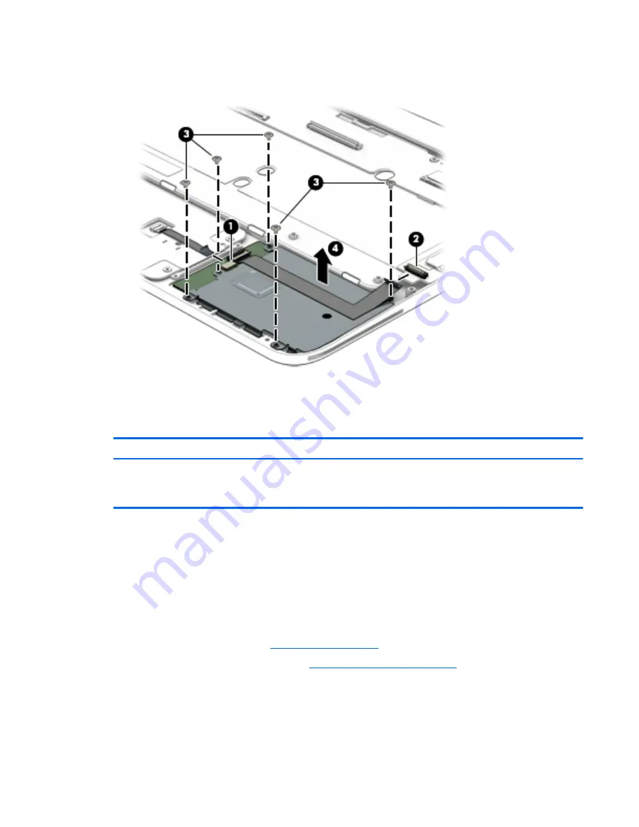
3.
Remove the five Phillips PM1.5×2.7 screws (3) that secure the smart card reader board to the top cover.
4.
Remove the smart card reader board (4).
Reverse this procedure to install the smart card reader board.
Connector board
Description
Spare part number
Connector board (includes USB port and DisplayPort)
NOTE:
The connector board spare part kit does not include the connector board cable. The
connector board cable is included in the Keyboard Base Cable Kit, spare part number 793721-001.
804350-001
Before removing the connector board, follow these steps:
1.
Shut down the keyboard base. If you are unsure whether the keyboard base is off or in Hibernation, turn
the keyboard base on, and then shut it down through the operating system.
2.
Disconnect all external devices connected to the keyboard base.
3.
Disconnect the power from the keyboard base by first unplugging the power cord from the AC outlet
and then unplugging the AC adapter from the keyboard base.
4.
Remove the bottom cover (see
Bottom cover on page 74
).
5.
Remove the keyboard base battery (see
Keyboard base battery on page 75
).
Remove the connector board:
Connector board
83